Unbuffered single inverter gate, New prod uc t, Absolute maximum ratings – Diodes 74AHC1GU04 User Manual
Page 3: Recommended operating conditions
74AHC1GU04
UNBUFFERED SINGLE INVERTER GATE
74AHC1GU04
Document number: DS35178 Rev. 1 - 2
3 of 8
March 2011
© Diodes Incorporated
NEW PROD
UC
T
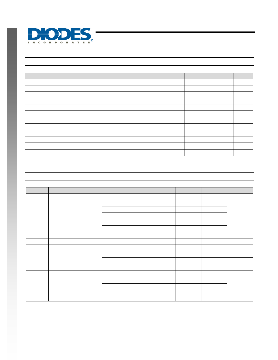
Absolute Maximum Ratings
(Note 2)
Symbol
Description
Rating
Unit
ESD HBM
Human Body Model ESD Protection
2
KV
ESD MM
Machine Model ESD Protection
200
V
V
CC
Supply Voltage Range
-0.5 to 6.5
V
V
I
Input Voltage Range
-0.5 to 6.5
V
V
O
Voltage applied to output in high or low state
-0.5 to V
CC
+0.5
V
I
IK
Input Clamp Current V
I
<0
-20 mA
I
OK
Output Clamp Current (V
O
< 0 or V
O
> V
CC
)
±20 mA
I
O
Continuous output current (V
O
= 0 to V
CC
)
±25 mA
I
CC
Continuous current through V
CC
50
mA
I
GND
Continuous current through GND
-50
mA
T
J
Operating Junction Temperature
-40 to 150
°C
T
STG
Storage Temperature
-65 to 150
°C
Notes: 2. Stresses beyond the absolute maximum may result in immediate failure or reduced reliability. These are stress values and device operation should be
within recommend values.
Recommended Operating Conditions
(Note 3)
Symbol
Parameter
Min
Max
Unit
V
CC
Operating Voltage
2
5.5
V
V
IH
High-level Input Voltage
V
CC
= 2V
1.7
V
V
CC
= 3V
2.4
V
CC
= 5.5V
4.4
V
IL
Low-level input voltage
V
CC
= 2V
0.3
V
V
CC
= 3V
0.6
V
CC
= 5.5V
1.1
V
I
Input Voltage
0
5.5
V
V
O
Output Voltage
0
V
CC
V
I
OH
High-level output current
V
CC
= 2V
-50
uA
V
CC
= 3.3V ± 0.3V
-3
mA
V
CC
= 5V ± 0.5V
-6
I
OL
Low-level output current
V
CC
= 2V
50
uA
V
CC
= 5V ± 0.5V
3
mA
V
CC
= 3V
6
T
A
Operating free-air
temperature
-40 85 ºC
Notes: 3. Unused inputs should be held at V
CC
or Ground.