Electrical characteristics, Operating characteristics – Diodes 74HCT595 User Manual
Page 5
74HCT595
Document number: DS35493 Rev. 3 - 2
5 of 11
July 2013
© Diodes Incorporated
Preliminary
74HCT595
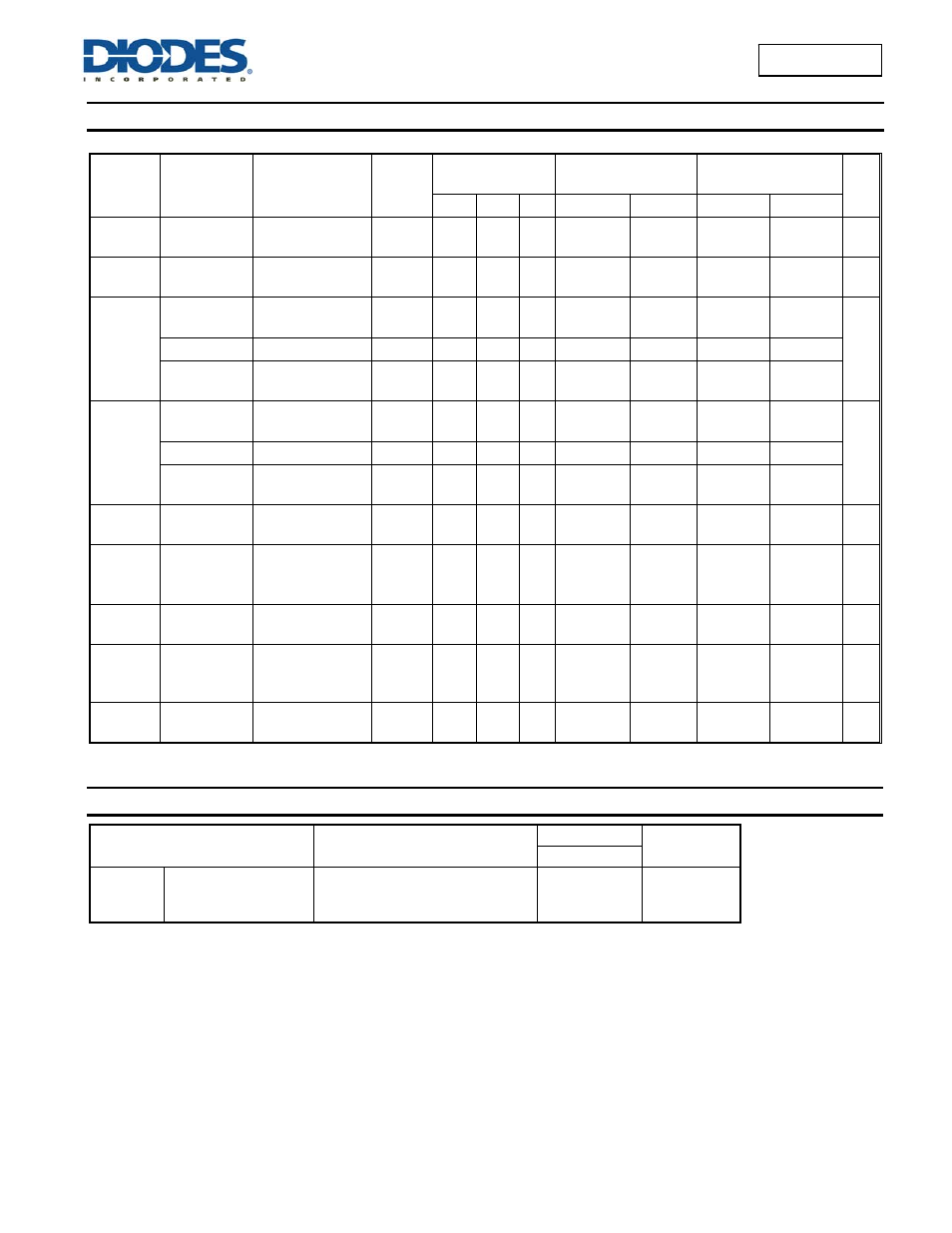
Electrical Characteristics
(@T
A
= +25°C°C, unless otherwise specified.)
Symbol Parameter Test
Conditions V
CC
T
A
= +25°C°C
T
A
= -40°C°C to
+85°C°C
T
A
= -40°C°C to
+125°C°C
Unit
Min Typ Max
Min
Max
Min
Max
V
IH
High-Level
Input Voltage
4.5V
to
5.5V
2.0
2.0
2.0
V
V
IL
Low-Level
Input Voltage
4.5V
to
5.5V
0.8
0.8
0.8 V
V
OH
High-Level
Output Voltage
I
OH
= -20μA
All outputs
4.5V 4.4 4.5
4.4
4.4
V
Q7S output
I
OH
= -4mA
4.5V
3.84 4.32
4.32
3.7
Qn Bus
Outputs
I
OH
= -6.0mA
4.5V
3.7 4.32
4.32
3.7
V
OL
Low-Level
Output Voltage
I
OL
= 20μA
All outputs
4.5V
0 0.1
0.1
0.1
V
Q7S output
I
OL
= 4mA
4.5V
0.15 0.33
0.33
0.4
Qn Bus
Outputs
I
OL
= 6.0mA
4.5V
.016 0.33
0.33
0.4
I
I
Input Current
V
I
=GND to
5.5V
5.5V
±0.1
± 1
± 1
μA
I
OZ
OFF-state
output current
Qn internal high or
low.
V
o
=Vcc or Gnd
5.5V
± 5
± 5
± 10
μA
I
CC
Supply Current
V
I
= GND or V
CC
I
O
=0
5.5V
8.0
80
160
μA
∆I
CC
Additional
Supply Current
per Input
V
I
= V
cc
-2.1V
I
O
=0
4.5V to
5.5V
100 450
450
490
μA
C
i
Input
Capacitance
V
i
= V
CC
or GND
5.5V
4 10
10
10 pF
Operating Characteristics
(@T
A
= +25°C°C, unless otherwise specified.)
Parameter
Test Conditions
V
CC
= 5V
Unit
TYP
C
pd
Power dissipation
capacitance
f = 1 MHz all outputs switching-no load
42
pF