Electrical characteristics, Switching characteristics – Diodes 74HC138 User Manual
Page 5
74HC138
Document number: DS35488 Rev.3 - 2
5 of 10
June 2013
© Diodes Incorporated
74HC138
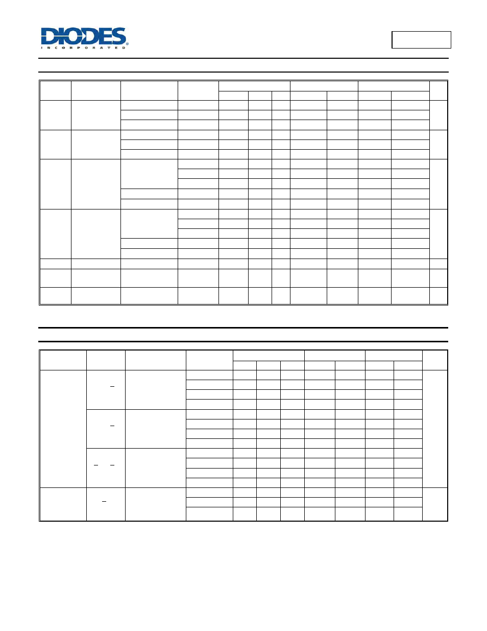
Electrical Characteristics
(@T
A
= +25°C, unless otherwise specified.)
Symbol Parameter Test
Conditions V
CC
T
A
= +25°C
T
A
= -40°C to +85°C
T
A
= -40°C to +125°C
Unit
Min Typ
Max
Min
Max Min
Max
V
IH
High-Level
Input Voltage
2.0V
1.5
1.2
1.5
1.5
V
4.5V
3.15
2.4
3.15
3.15
6.0V
4.2
3.2
4.2
4.2
V
IL
Low-Level
Input Voltage
2.0V
0.8
0.5
0.5
0.5
V
4.5V
2.1
1.35
1.35
1.35
6.0V
2.8
1.8
1.8
1.8
V
OH
High-Level
Output Voltage
I
OH
= -20
μA
All outputs
2.0V
1.9
2.0
1.9
1.9
V
4.5V
4.4
4.5
4.4
4.4
6.0V
5.9
6.0
5.9
5.9
I
OH
= -4 mA
4.5V
3.98
4.32
3.84
3.7
I
OH
= -5.2 mA
6.0V
5.48
5.81
5.34
5.2
V
OL
Low-Level
Output Voltage
I
OL
= 20
μA
All outputs
2.0V
0
0.1
0.1
0.1
V
4.5V
0
0.1
0.1
0.1
6.0V
0
0.1
0.1
0.1
I
OL
= 4 mA
4.5V
0.15
0.26
0.33
0.4
I
OL
= 5.2 mA
6.0V
0.16
0.26
0.33
0.4
I
I
Input Current
V
I
=GND or 6.0V
6.0V
±0.1
± 1
± 1
μA
I
CC
Supply Current
V
I
= GND or V
CC
I
O
= 0
6.0V
8.0
80
160
μA
C
i
Input
Capacitance
V
i
= V
CC
or GND
6.0V
4 10
10
10 pF
Switching Characteristics
Symbol /
Parameter
Pins
Test Conditions
V
CC
T
A
= +25°C
-40°C to +85°C
-40°C to +125°C
Unit
Min Typ Max Min
Max Min Max
t
PLH,
t
PLH
Propagation
Delay
An to Yn
Figure 1
2.0V
41 150
190
225
ns
4.5V
15 30
38
45
5.0V
12
6.0V
12 26
33
38
E3 to Yn
Figure 1
2.0V
47 150
190
225
4.5V
17 30
38
45
5.0V
14
6.0V
14 26
33
38
En to Yn
Figure 1
2.0V
47 150
190
225
4.5V
17 30
38
45
5.0V
14
6.0V
14 26
33
38
t
TLH,
t
THL
Transition
Time
Yn
Figure 1
2.0V
19 75
95
110
ns
5.0V
7 15
19
22
6.0V
6 13
16
19