New prod uc t 74ahct08, Recommended operating conditions, Electrical characteristics – Diodes 74AHCT08 User Manual
Page 3: Operating characteristics, Switching characteristics
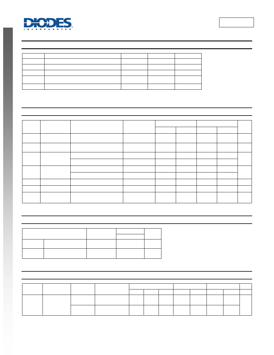
74AHCT08
Document number: DS35351 Rev. 3 - 2
3 of 8
January 2013
© Diodes Incorporated
NEW PROD
UC
T
74AHCT08
Recommended Operating Conditions
(Note 5) (@T
A
= +25°C, unless otherwise specified.)
Symbol Parameter
Min
Max
Unit
V
CC
Supply Voltage
4.5
5.5
V
V
I
Input Voltage
0
5.5
V
V
O
Output Voltage
0
V
CC
V
Δt/ΔV
Input transition rise or fall rate
20
ns/V
T
A
Operating Free-Air Temperature
-40
+125
°C
Note:
5. Unused inputs should be held at V
CC
or Ground.
Electrical Characteristics
(@T
A
= +25°C, unless otherwise specified.)
Symbol
Parameter
Test Conditions
V
CC
T
A
= -40°C to +85°C
T
A
= -40°C to +125°C
Unit
Min
Max
Min
Max
V
IH
High-Level Input
Voltage
4.5V to 5.5V
2.0
2.0
V
V
IL
Low-Level Input
Voltage
4.5V to 5.5V
0.8
0.8
V
V
OH
High-Level
Output Voltage
I
OH
= -50μA
4.5V
4.4 4.4
V
I
OH
= -8mA
4.5V 3.80 3.70
V
OL
Low-Level Output
Voltage
I
OL
= 50μA
4.5V
0.1 0.1
V
I
OL
= 8mA
4.5V
0.44 0.55
I
I
Input Current
V
I
=GND to 5.5V
3.6V
±1 ±2
μA
I
CC
Supply Current
V
I
= GND or V
CC,
I
O
= 0
3.6V
20
40
μA
ΔI
CC
Additional Supply
Current
One input at V
CC
-2.1V
Other pins at V
CC
or GND
5.5V
1.35 5
mA
Operating Characteristics
Parameter
Test
Conditions
V
CC
= 5.5V
Unit
Typ
C
pd
Power Dissipation
Capacitance per Gate
f = 1MHz
14.8
pF
C
i
Input Capacitance
V
i
= V
CC
– or
GND
4.0 pF
Switching Characteristics
Symbol
Parameter
Test
Conditions
V
CC
T
A
= +25°C
-40°C to +85°C
-40°C to +125°C
Unit
Min Typ Max Min Max Min Max
t
PD
Propagation
Delay A
N
to Y
N
Figure 1
C
L
= 15pF
4.5V to 5.5V
0.5
3.4
6.9
0.5
8.0
0.5
9.0
ns
Figure 1
C
L
= 50pF
4.5V to 5.5V
0.5
4.9
10.0
0.5
10.0
0.5
11.0