Ah180, Micropower omnipolar hall-effect sensor switch, Absolute maximum ratings – Diodes AH180 User Manual
Page 3: Recommended operating conditions, Electrical characteristics
AH180
MICROPOWER OMNIPOLAR HALL-EFFECT SENSOR
SWITCH
AH180
Document number: DS31023 Rev. 17 - 2
3 of 13
July 2010
© Diodes Incorporated
Absolute Maximum Ratings
(T
A
= 25
°C)
Symbol
Characteristics
Values
Unit
Vdd Supply
voltage
7
V
B
Magnetic flux density
Unlimited
Ts
Storage Temperature Range
-65 to +150
°C
P
D
Package Power Dissipation
SIP-3L 550
mW
SC59-3L/ DFN2020-6/
DFN2020-3
230 mW
T
J
Maximum Junction Temperature
150
°C
Recommended Operating Conditions
Symbol
Parameter
Conditions
Min
Max
Unit
Vdd
Supply Voltage
Operating
2.5
5.5
V
T
A
Operating Ambient Temperature
Operating
-40
85
°C
Electrical Characteristics
(T
A
= 25
°C, Vdd
= 3V; unless otherwise specified)
Symbol
Characteristic
Conditions
Min
Typ.
Max
Unit
Vout
Output On Voltage
Iout =1mA
⎯
0.1 0.3 V
Ioff
Output Leakage Current
Vout =5.5V, Output off
⎯
<
0.1
1 µA
Idd(en)
Supply Current
Chip enable, T
A
= 25
°C, Vdd = 3V
⎯
3
6
mA
Idd(en)
Chip enable, T
A
= -40~85
°C,
Vdd = 2.5~5.5V
⎯
3
9
mA
Idd(dis)
Chip disable, T
A
= 25
°C, Vdd = 3V
⎯
5 10 µA
Idd(dis)
Chip disable, T
A
= -40~85
°C,
Vdd = 2.5~5.5V
⎯
5 15 µA
Idd(avg)
Average supply current,
T
A
= 25
°C, Vdd = 3V
⎯
8 16 µA
Idd(avg)
Average supply current,
T
A
= -40~85
°C, Vdd = 2.5~5.5V
⎯
8 24 µA
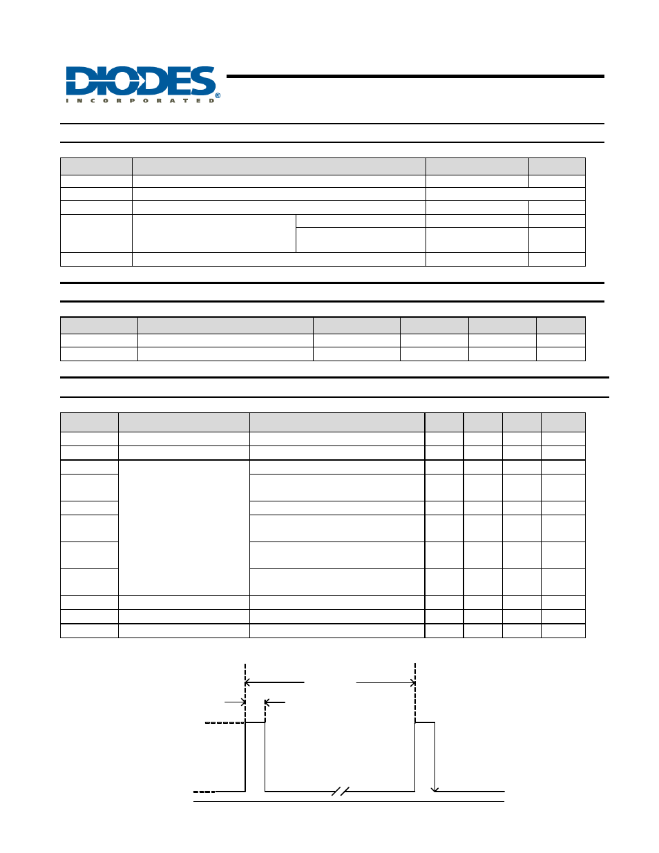
Tawake
Awake Time
(Note 2)
⎯
75 125 µs
Tperiod Period
(Note
2)
⎯
75 125 ms
D.C. Duty
Cycle
⎯
0.1
⎯
%
Notes: 2. When power is initially turned on, Vdd must be within its correct operating range (2.5V to 5.5V) to guarantee the output sampling.
The output state is valid after the second operating phase (typical 150ms).
Idd (dis)
Idd(en)
Tawake
Tperiod
0
Sample and output
latched