Data sheet, Figure 10, Application 1 (default) – Diodes AM4962 User Manual
Page 11: Hall am4962
Data Sheet
SINGLE PHASE FULL WAVE DIRECT PWM MOTOR DRIVER AM4962
Apr. 2011 Rev. 1. 2 BCD Semiconductor Manufacturing Limited
11
0
10
20
30
40
50
60
70
80
90
100
0
20
40
60
80
100
Max. Duty Cycle
O
u
tput
Dut
y
Cyc
le (
%
)
Input PWM Duty Cycle (%)
Min. Duty Cycle
Slope K
OUT2
OUT1
VCC
GND
VMIN
CT
PWM
RADJ
CF
HIN-
FG
HB
RD
HIN+
Hall
AM4962
D1
C1
1
μF
VCC
L1
C3
1
μF
C2
0.47
μF
1 (1)
PGND
V+
2 (3)
3 (4)
4 (5)
5 (6)
6 (7)
7 (8)
8 (9)
9 (10)
10 (11)
11 (12)
12 (13)
13 (14)
14 (15)
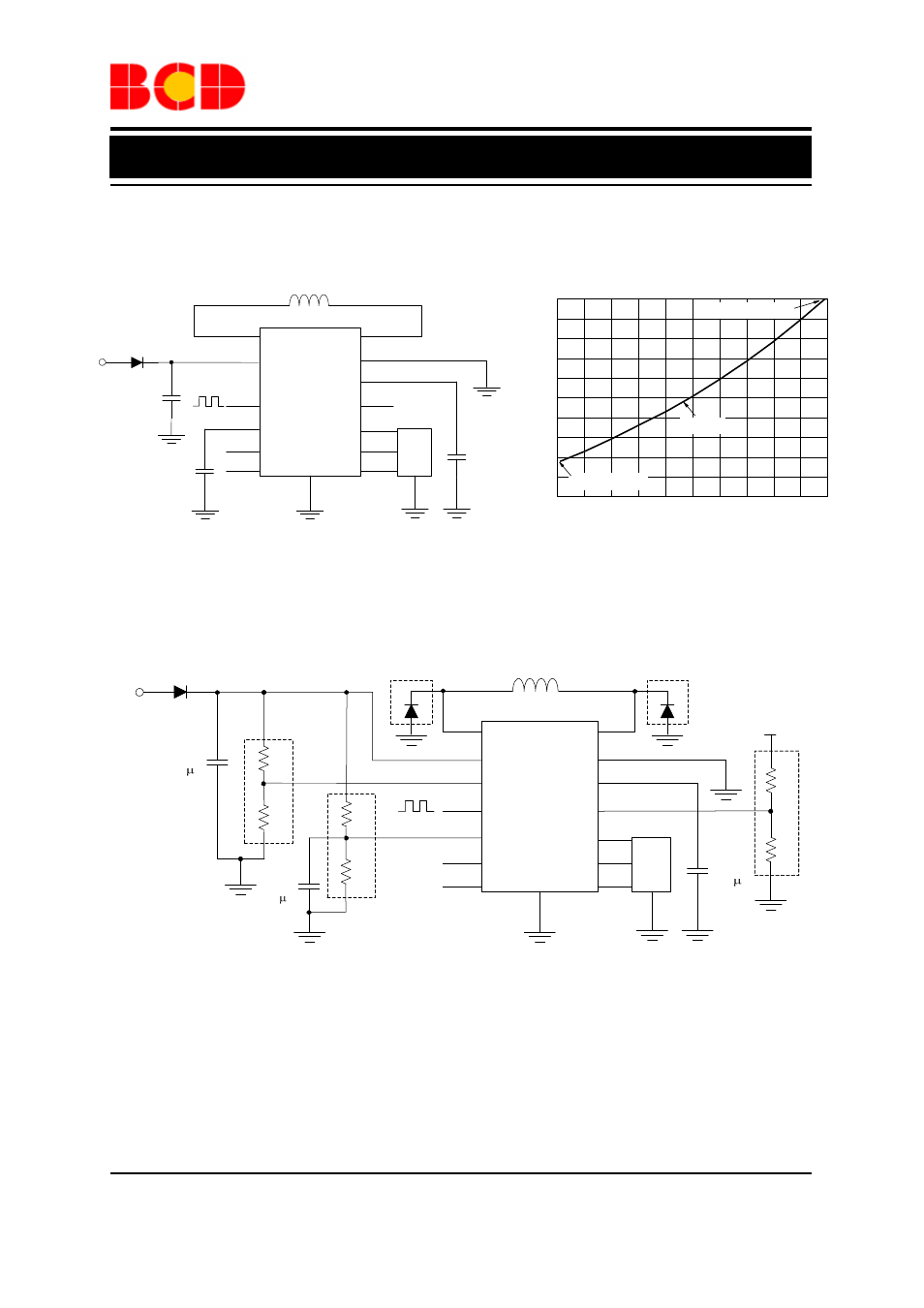
Typical Application (Note 4)
Figure 10
Application 1 (Default)
R1
R2
D3
OUT2
OUT1
VCC
GND
VMIN
CT
PWM
RADJ
CF
HIN-
FG
HB
RD
HIN+
Hall
AM4962
D1
C1
1 F
VCC
L1
C3
1 F
C2
0.47 F
1 (1)
PGND
R3
R4
V+
R5
R6
V+
2 (3)
3 (4)
4 (5)
5 (6)
6 (7)
7 (8)
8 (9)
9 (10)
10 (11)
11 (12)
12 (13)
13 (14)
14 (15)
D2
Application 2 (Slope K and Minimum/Maximum Duty Adjustable)
Note: D2 and D3 are recommended to be used when the current in coil L1 is higher than 300mA.
Figure 11. Typical Applications of AM4962
- PDS3200 (5 pages)
- PDS340 (5 pages)
- PDS340Q (5 pages)
- PDS360 (5 pages)
- PDS360Q (5 pages)
- PDS4150 (4 pages)
- PDS3100Q (5 pages)
- PDS3100 (5 pages)
- PDS1240CTL (5 pages)
- PDS1045 (5 pages)
- PDS1040L (5 pages)
- PDS1040CTL (5 pages)
- PDS1040 (5 pages)
- PD3S230L (5 pages)
- PD3S230H (3 pages)
- PDS5100Q (5 pages)
- PDS835L (5 pages)
- PDS760 (5 pages)
- PDS560 (5 pages)
- PDS540 (5 pages)
- PDS5100H (5 pages)
- PDS5100 (5 pages)
- PDS4200H (6 pages)
- SBL3060CTP (4 pages)
- SBL30L30CT (3 pages)
- SBL3045CTP (4 pages)
- SBL3040CTP (4 pages)
- SBL2060CTP (4 pages)
- SBL2030CT - SBL2060CT (3 pages)
- SBL2045CTP (4 pages)
- SBL1060CTP (4 pages)
- SBL1040CTP (4 pages)
- SBG3030CT - SBG3045CT (5 pages)
- SB520 - SB560 (3 pages)
- SB370 - SB3100 (3 pages)
- SB320 - SB360 (3 pages)
- SBR10U100CT (5 pages)
- SBR10U150CT (5 pages)
- SBR10A45SP5 (5 pages)
- SBR1060CT (5 pages)
- SBR1045SP5 (5 pages)
- SBR1045SD1 (4 pages)
- SBR1045D1 (5 pages)
- SBR1045CTL (4 pages)
- SBR1040CT (5 pages)