Ah5795, New prod uc t absolute maximum ratings, Recommended operating conditions – Diodes AH5795 User Manual
Page 4: Electrical characteristics
AH5795
SINGLE PHASE HALL EFFECT LATCH SMART
FAN MOTOR CONTROLLER
AH5795
Document number: DS35277 Rev. 1 - 2
4 of 13
August 2011
© Diodes Incorporated
NEW PROD
UC
T
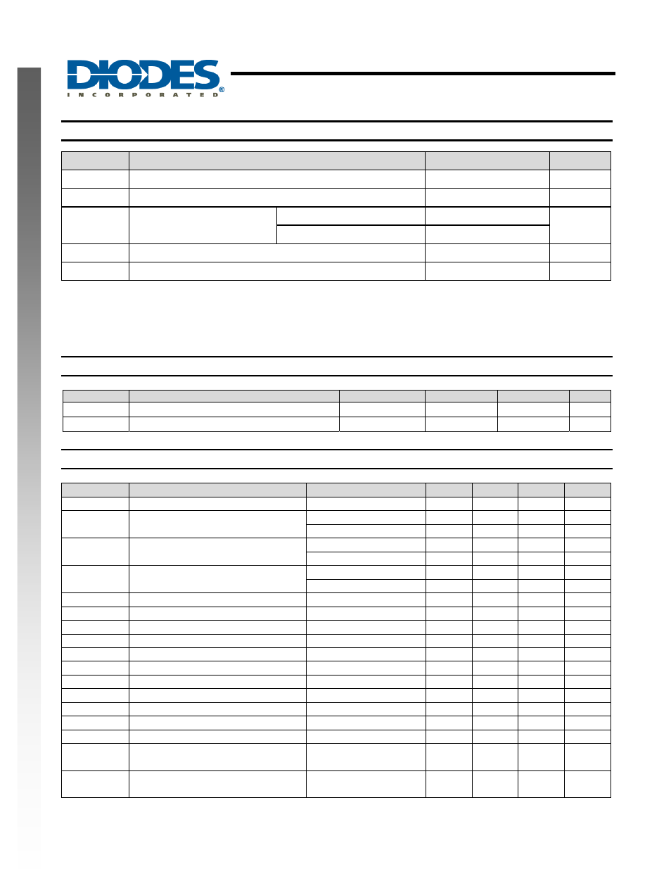
Absolute Maximum Ratings
(T
A
= 25
°C, unless otherwise noted, Note 4)
Symbol
Characteristics
Values
Unit
Vdd
Supply voltage
7
V
I
O(PEAK)
Maximum Output Current (Peak)
1000mA
mA
P
D
Power
Dissipation
TSOT23-6 650
mW
DFN2020C-6
780 (Note 5)
T
ST
Storage Temperature Range
-65 ~ 150
o
C
ESD HBM
Human Body Model (HBM) ESD Protection
4
kV
Notes:
4. Stresses greater than the 'Absolute Maximum Ratings' specified above, may cause permanent damage to the device. These are stress ratings
only; functional operation of the device at these or any other conditions exceeding those indicated in this specification is not implied. Device
reliability may be affected by exposure to absolute maximum rating conditions for extended periods of time
5. DFN2020C-6 exposed pad soldered to minimum recommended landing pads (see Package Outline Dimension section) on a two-layer 2oz.
copper FR4 PCB (1.6mm thickness) with no thermal vias in exposed PADs or any copper flood connecting to the landing pattern of the
exposed pad.
Recommended Operating Conditions
(T
A
= 25
°C)
Symbol
Parameter
Conditions
Min
Max
Unit
V
DD
Supply
Voltage
Operating
1.8
6.0
V
T
A
Operating Ambient Temperature Range
Operating
-40 105
o
C
Electrical Characteristics
(T
A
= 25
°C, V
DD
= 5V)
Symbol
Characteristics
Conditions
Min
Typ.
Max
Unit
IDD
Supply Current
No Load
-
2.2
-
mA
V
OH
Output Voltage High
I
OUT
= 300mA
4.70
4.88
-
V
I
OUT
= 500mA
4.5
4.8
-
V
V
OL
Output Voltage Low
I
OUT
= 300mA
-
0.12
0.3
V
I
OUT
= 500mA
-
0.2
0.5
V
Voh+Vol
Output voltage of N- and PMOS
combined
I
OUT
= 300mA
0.3
0.6
V
I
OUT
= 500mA
0.5
V
T
SW
Output Switching Slope Duration
17
Ω load on out1/out2
-
200
-
μs
I
LEAK
FG Output Leakage Current
-
-
5
μA
V
FGOL
FG Output Voltage Low
I
FG
= 5mA
-
-
0.4
V
T
ON
On Time
350
500
650
ms
R
DR
Duty Ratio
T
OFF
/ T
ON
-
10
-
V
PWMH
PWM Input H Level
-
0.5 Vdd
-
Vdd
V
V
PWML
PWM Input L Level
-
0
-
0.14 Vdd
V
I
PWMH
PWM Input current H Level
PWM=Vdd
0
uA
I
PWMH
PWM Input current L Level
PWM=GND
-10
uA
F
PWM
PWM Input Frequency
-
0.02
-
50
KHz
D
PWM_MIN
Output minimum duty ratio
Motor rotating;
10%
100
%
Tj_
SDN_TH
IC junction temperature thermal
shutdown threshold
175
o
C
Tj_
SDN_HYST
IC junction temperature thermal
shutdown hysteresis
25
o
C