Preliminary datasheet, White led step-up converter ap3033, Pin configuration pin description – Diodes AP3033 User Manual
Page 2
Preliminary Datasheet
2
Jan. 2010 Rev. 1. 0
BCD Semiconductor Manufacturing Limited
WHITE LED STEP-UP CONVERTER AP3033
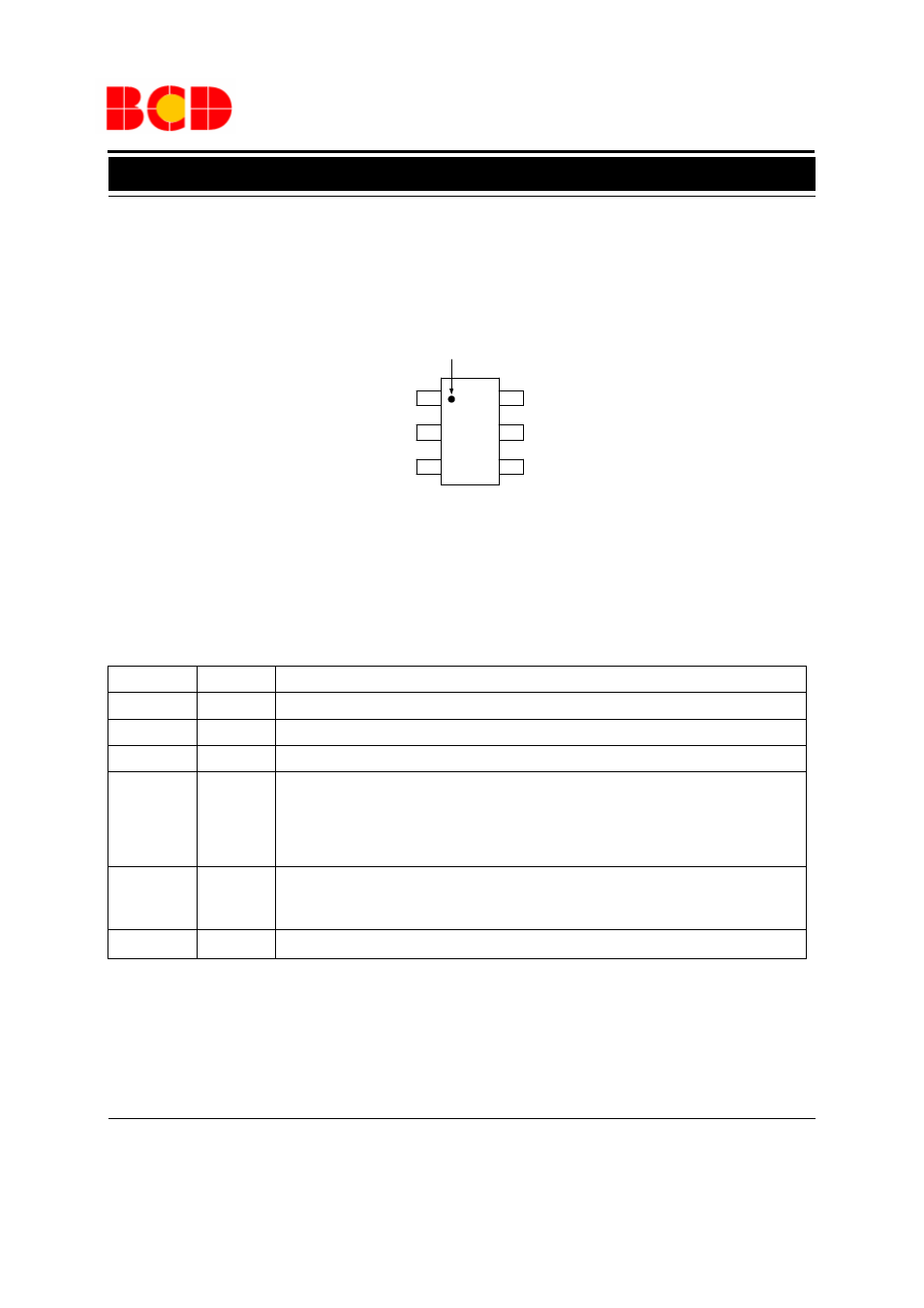
Figure 2. Pin Configuration of AP3033 (Top View)
Pin Configuration
Pin Description
Pin Number
Pin Name
Function
1
SW
Switch Pin. Connect external inductor and Schottky
2
GND Ground
Pin
3
FB Voltage
Feedback
Pin.
Reference voltage is 200mV
4
CTRL
Enable and Dimming Control Pin. Connect to a high input to enable the IC or a low input to
disable the IC. If logic low time is
more than about 0.45ms and then enable the IC, the
AP3033 will soft start to protect system departments. If logic low time is less than about
0.45ms and then enable the IC, the AP3033 will hold on standby mode and start directly to
achieve high frequency dimming
5
OV
Over-voltage Protection Input Pin. Connect to the output directly or connect to the V
OUT
through a resistor divider to set the OVP voltage. On OVP condition, the output voltage will
be clamped
6
V
IN
Input Supply Pin. Must be locally bypassed
(TSOT-23-6)
SW
GND
FB
V
IN
OV
CTRL
KT Package
1
2
3
4
5
Pin 1 Dot by Marking
6