Ap8801, 500ma led step-down converter, Pin descriptions – Diodes AP8801 User Manual
Page 2: Functional block diagram, Absolute maximum ratings
AP8801
500mA LED STEP-DOWN CONVERTER
AP8801
Document number: DS31765 Rev. 7 - 2
2 of 14
June 2012
© Diodes Incorporated
Pin Descriptions
Pin Name
Functions
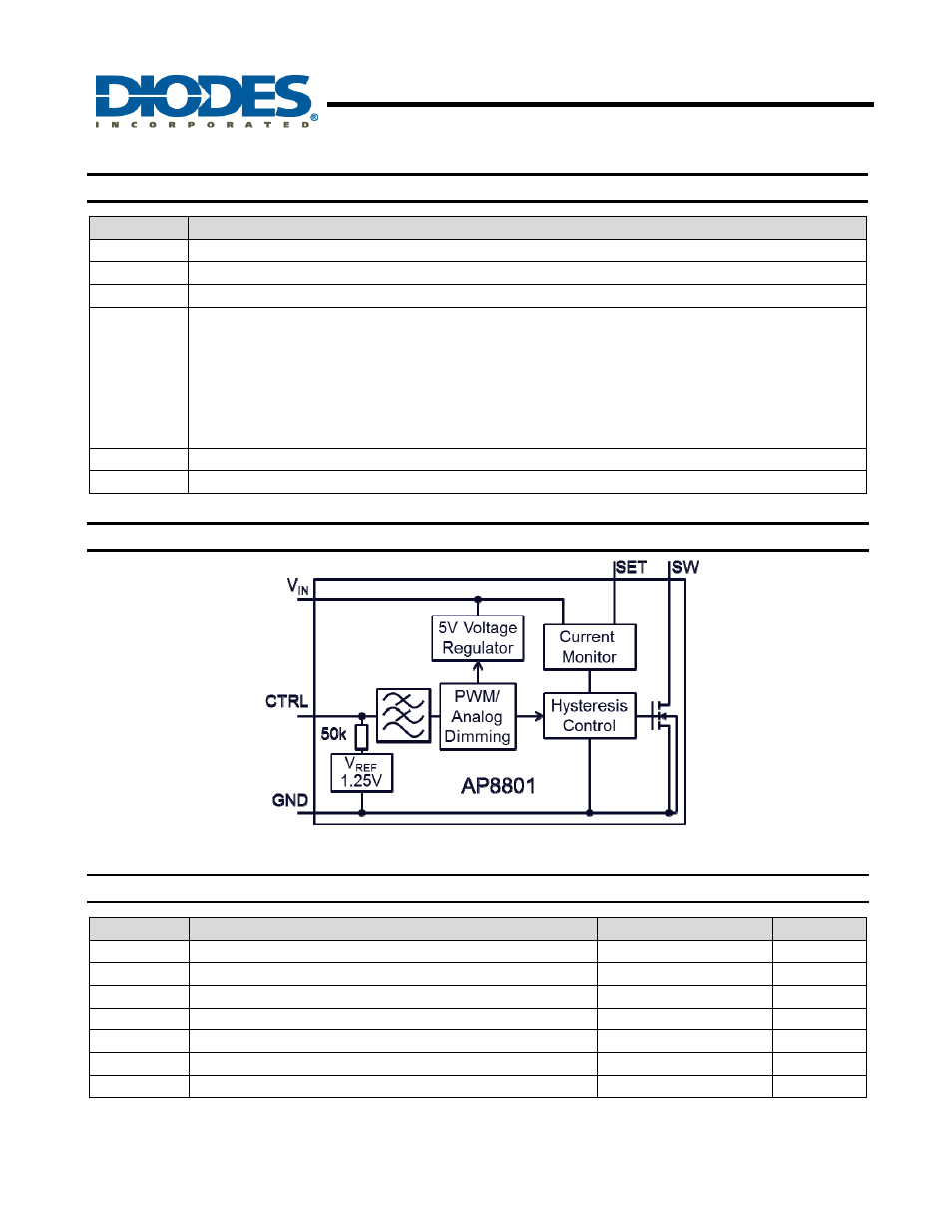
SW
Switch Pin. Connect inductor/freewheeling diode here, minimizing track length at this pin to reduce EMI.
GND GND
pin
SET
Set Nominal Output Current Pin. Configure the output current of the device.
CTRL
Dual Function Dimming Control Pin.
• Input voltage of 0.2V or lower forces the device into low current standby mode and shuts off the output.
• A PWM signal (driven by an open-drain/collector source) allows the output current to be adjusted over a wide
range up to 100%.
• An analog voltage between 0.3V and 2.5V adjusts the output current between 25% and 200% of the current set
by 0.2V/R
S
.
The input impedance is about 50k
Ω, and if the pin is left open V
CTRL
= V
REF
V
IN
Input Supply Pin. Must be locally bypassed.
NC No
connection
Functional Block Diagram
Fig. 1 Block Diagram
Absolute Maximum Ratings
Symbol
Parameter
Rating
Unit
V
IN
V
IN
pin voltage
-0.3 to +50
V
V
SW
SW voltage
-0.3 to +50
V
V
CTRL
CTRL Pin Input Voltage
-0.3 to +6
V
V
SENSE
SET Voltage
+0.3 to -5
V
T
J
Junction Temperature
150
o
C
T
LEAD
Lead Temperature Soldering
300
o
C
T
ST
Storage Temperature Range
-65 to +150
o
C
Caution:
Stresses greater than the 'Absolute Maximum Ratings' specified above, may cause permanent damage to the device. These are stress ratings only;
functional operation of the device at these or any other conditions exceeding those indicated in this specification is not implied. Device reliability may
be affected by
exposure to absolute maximum rating conditions for extended periods of time.
Semiconductor devices are ESD sensitive and may be damaged by exposure to ESD events. Suitable ESD precautions should be taken when
handling and transporting these devices.