Al8806, Application information – Diodes AL8806 User Manual
Page 11
AL8806
Document number: DS35144 Rev. 5 - 2
11 of 15
July 2013
© Diodes Incorporated
AL8806
Application Information
(cont.)
PCB Layout
When laying out the PCB for the AL8806 the following should be observed:
1.
The decoupling capacitor C1 has to be placed as close as possible to V
IN
2.
The sense resistor, R
SET
, has to be placed as close as possible to V
IN
and SET
3.
The anode of the freewheel diode (D1), the SW pin and the inductor have to be placed as close as possible to each other to avoid ringing.
AL8806
V
IN
SE
T
CTRL
SW
GN
D
C2
R
SET
C1
D1
L1
To avoid
radiated EMI
keep dashed
tracks as
short as
possible
Figure 6 PCB Layout
The AL8806 has two evaluation boards available on request (AL8806EV4 and AL8806EV6). Information can be found on the Diodes website and
from a Diodes’ sales representative.
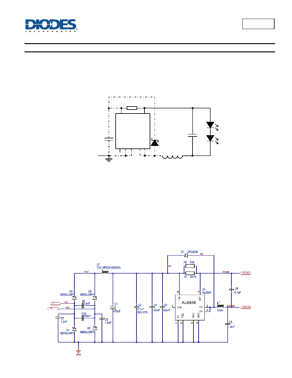
Application Example
A typical application example for the AL8806 is the MR16 lamp; which normally operate from 12V
DC
or 12V
AC
supplies, using conventional
electromagnetic transformers or electronic transformers.
As a replacement for MR16 halogen lamps, LED lamps offer a more energy efficient solution - radiating no heat and no Ultra Violet light. The low
thermal impedance of the AL8806 and its 1.5A switch capability allows it drive some of the latest multi-die LEDs; which increases the lamp’s
luminance.
This application example is intended to fit into the base connector space of an MR16 style LED lamp. The design has been optimized for part count
and thermal performance for a multi-die LED in the Lens section as well as EMI conformance.
Figure 7 MR16 Schematic