Ap2127 – Diodes AP2127 User Manual
Page 13
AP2127
Document number: DS36478 Rev. 3 - 2
2 of 27
January 2014
© Diodes Incorporated
AP2127
A Product Line of
Diodes Incorporated
Application Notes
(cont.)
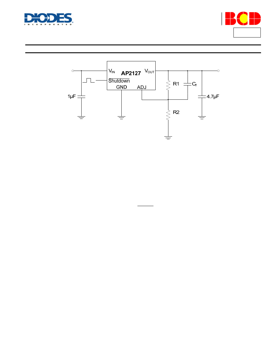
Figure 1. Application Circuit with Feed-forward Capacitor
Current Limit Protection
When output current at V
OUT
pin is higher than current limit threshold, the current limit protection will be triggered and clamp the output current to
prevent over-current and to protect the regulator and load from damaged due to overheating.
Short Circuit Protection
When V
OUT
pin is shorted to GND, short circuit protection will be triggered and clamp the output current to approximately 50mA.
Auto discharge with Shutdown Version
For shutdown version, an auto discharge MOSFET with R
DS(ON)
of 60Ω typical is integrated between V
OUT
and GND pins, which can discharge the
charge of the output capacitors quickly when turning off AP2127 with Shutdown pin.
Thermal Consideration
Internal thermal protection circuitry of AP2127 is used to protect device during overload conditions. For continuous operation, ensure not to
exceed the operating junction temperature range of +125°C.
The power dissipation definition in the device is:
P
D
= (V
IN
- V
OUT
) x I
OUT
+ V
IN
x I
Q
The maximum power dissipation depends on the thermal resistance of IC package, PCB layout and the surrounding airflow. The maximum power
dissipation can also be calculated as:
P
D(MAX)
= (T
J(MAX)
- T
A
) / θ
JA
The maximum power dissipation for SOT-23-5 package (least copper size) at T
A
= +25°C can be calculated as:
P
D(MAX)
= (125°C - 25°C) / (250°C/W) = 0.4W