Ap1122, 1a low dropout positive regulator, Typical application circuit – Diodes AP1122 User Manual
Page 2: Pin descriptions, Functional block diagram
AP1122
1A LOW DROPOUT POSITIVE REGULATOR
AP1122
Document number: DS31012 Rev. 9 - 2
2 of 11
May 2010
© Diodes Incorporated
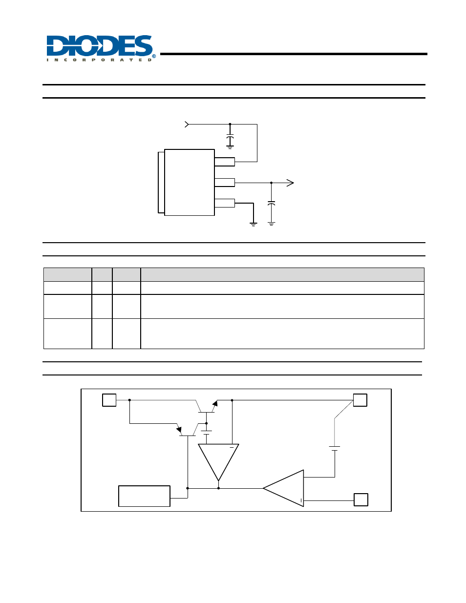
Typical Application Circuit
C2
100uF
2.5V
1.2V/1A
Tab is V
OUT
V
IN
V
OUT
GND
C1
100uF
Pin Descriptions
Pin Name
I/O
Pin #
Description
GND I
1
Ground
Pin
V
OUT
O
2
The output of the regulator. A minimum of 10uF capacitor (0.15
Ω ≤ ESR ≤ 20Ω)
must be connected from this pin to ground to insure stability.
V
IN
I
3
The input pin of regulator. Typically a large storage capacitor is connected from
this pin to ground to insure that the input voltage does not sag below the
minimum dropout voltage during the load transient response.
Functional Block Diagram
3
Thermal
Shutdown
1
2
V
OUT
GND
1.2V
+
+
CURRENT
LIMIT
V
IN
+
+
See also other documents in the category Diodes Hardware:
- PDS3200 (5 pages)
- PDS340 (5 pages)
- PDS340Q (5 pages)
- PDS360 (5 pages)
- PDS360Q (5 pages)
- PDS4150 (4 pages)
- PDS3100Q (5 pages)
- PDS3100 (5 pages)
- PDS1240CTL (5 pages)
- PDS1045 (5 pages)
- PDS1040L (5 pages)
- PDS1040CTL (5 pages)
- PDS1040 (5 pages)
- PD3S230L (5 pages)
- PD3S230H (3 pages)
- PDS5100Q (5 pages)
- PDS835L (5 pages)
- PDS760 (5 pages)
- PDS560 (5 pages)
- PDS540 (5 pages)
- PDS5100H (5 pages)
- PDS5100 (5 pages)
- PDS4200H (6 pages)
- SBL3060CTP (4 pages)
- SBL30L30CT (3 pages)
- SBL3045CTP (4 pages)
- SBL3040CTP (4 pages)
- SBL2060CTP (4 pages)
- SBL2030CT - SBL2060CT (3 pages)
- SBL2045CTP (4 pages)
- SBL1060CTP (4 pages)
- SBL1040CTP (4 pages)
- SBG3030CT - SBG3045CT (5 pages)
- SB520 - SB560 (3 pages)
- SB370 - SB3100 (3 pages)
- SB320 - SB360 (3 pages)
- SBR10U100CT (5 pages)
- SBR10U150CT (5 pages)
- SBR10A45SP5 (5 pages)
- SBR1060CT (5 pages)
- SBR1045SP5 (5 pages)
- SBR1045SD1 (4 pages)
- SBR1045D1 (5 pages)
- SBR1045CTL (4 pages)
- SBR1040CT (5 pages)