Data sheet, Li-ion/li polymer battery charger aur9801c, Description of charger operation – Diodes AUR9801C User Manual
Page 8
Data Sheet
Li-ion/Li Polymer Battery Charger AUR9801C
Aug. 2012 Rev. 1. 0 BCD Semiconductor Manufacturing Limited
8
Description of Charger Operation
The AUR9801C initiates a charger operation when
attached with a voltage source device or adaptor.
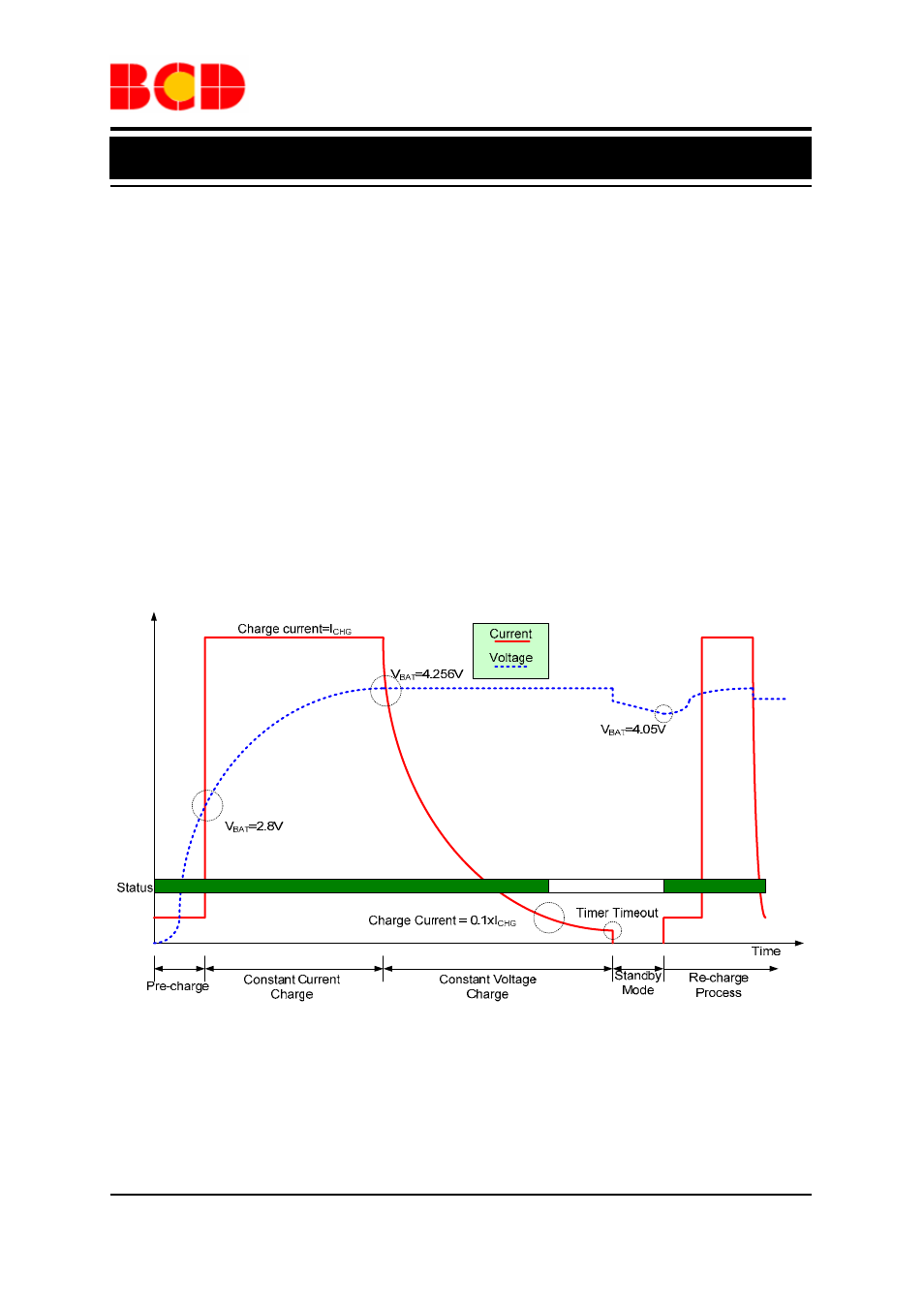
Figure 7 shows a typical charge profile when the
chip operates as a conventional linear charger with
a constant voltage source. The charging current is
set by an external resistor up to 1A. The target
charging voltage is 1% accurate over the specified
range.
The charger IC resets internal operational circuits
when internal Power-on-reset (POR) signal
becomes valid. V2P8 presents a voltage reference
output source capable of driving 2mA current after
POR. Other indication output pins are /STATUS
and /FAULT. The /STATUS is active low as an
open-drain type to indicate a charging cycle and
valid till the End-off-charge (EOC). The /FAULT
output signal becomes low to signal any occurred
fault conditions such as a charging time fault.
When charge with a current-limited adapter,
AUR9801C should be programmed with I
REF
over
the upper limit of I
LIM
. A typical charge profile is
displayed in Figure 8 for minimizing power
dissipation during CC mode. The worst power
dissipation is often at the start of CV mode,
although thermal fold-back conditions could still
occur in this application case.
Figure 7. A Typical Charge Profile as a Conventional Linear Charger