Typical applications circuit, Pin descriptions – Diodes AP2172A User Manual
Page 2
AP2162A/ AP2172A
Document number: DS32192 Rev. 4 - 2
2 of 16
April 2013
© Diodes Incorporated
AP2162A/ AP2172A
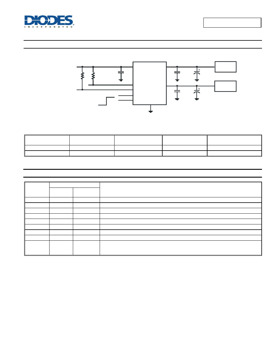
Typical Applications Circuit
1uF
IN
GND
EN2
OUT1
ON
10uF*
Power Supply
2.7V to 5.5V
1uF
OFF
FLG 1
Load
10k
10k
FLG 2
EN1
OUT2
10uF*
1uF
Load
AP 2172 A Enable Active High
Note: * USB 2.0 requires 120 F per hub
Available Options
Part Number
Channel
Enable Pin
(EN)
Current Limit
(typ)
Recommended Maximum
Continuous Load Current
AP2162A 2 Active
Low
1.4A
1.0A
AP2172A 2 Active
High
1.4A
1.0A
Pin Descriptions
Pin Name
Pin Number
Function
SO-8
MSOP-8EP
U-DFN3030-8
GND 1
1
Ground
IN
2
2
Voltage input pin
EN1
3
3
Switch 1 enable input, active low (AP2142A) or active high (AP2152A)
EN2
4
4
Switch 2 enable input, active low (AP2142A) or active high (AP2152A)
FLG2
5
5
Switch 2 over-current and over-temperature fault report; open-drain flag is active low when triggered
OUT2
6
6
Switch 2 voltage output pin
OUT1
7
7
Switch 1 voltage output pin
FLG1
8
8
Switch 1 over-current and over-temperature fault report; open-drain flag is active low when triggered
Exposed Pad
—
Exposed Pad
Exposed Pad:
It should be connected to GND and thermal mass for enhanced thermal impedance.
It should not be used as electrical ground conduction path.