Preliminary datasheet, Electrical characteristics, I- i v - v – Diodes AP3202 User Manual
Page 5
Preliminary Datasheet
380kHz, 2A Asynchronous DC-DC Buck Converter AP3202
Mar. 2011 Rev. 1. 2 BCD Semiconductor Manufacturing Limited
5
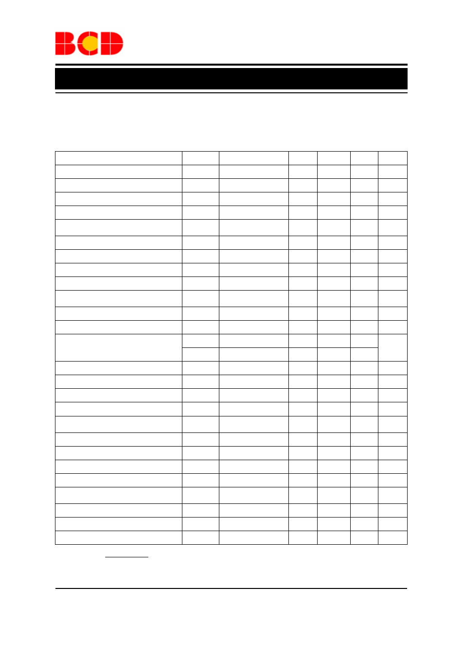
Electrical Characteristics
V
IN
=V
EN
=12V, V
OUT
=3.3V, unless otherwise specified. Specification with standard typeface are for
T
A
=25
o
C, and those in boldface type apply over the full operating temperature range (T
A
=-40
o
C to 85
o
C)
Parameter Symbol
Conditions
Min
Typ
Max
Unit
Input Voltage
V
IN
4.75
18 V
Quiescent Current
I
Q
V
FB
=1.4V, V
EN
=2V 1.0 1.5
mA
Shutdown Supply Current
I
SHDN
V
EN
=0V
1
10
µA
Feedback Voltage
V
FB
1.185
1.222 1.258 V
Feedback Over Voltage
Threshold
V
FBOV
1.48
V
Feedback SCP Voltage Threshold
V
FBSCP
0.6
V
Feedback Bias Current
I
FB
V
FB
=1V -0.1
0.1
µA
High-side Switch On-resistance (Note 2)
R
DSONH
I
SW
=0.5A
0.22
Ω
Low-side Switch On-resistance (Note 2)
R
DSONL
I
SW
=0.05A
10
Ω
High-side Switch Leakage Current
I
LEAKH
V
IN
=18V, V
EN
=0V
V
SW
=0V
0.1
10
µA
High-side Switch Current Limit
I
LIMH
2.8 3.8
A
Low-side Switch Current Limit
I
LIML
From drain to source
0.15
A
V
ENH
1.5
EN Pin Threshold
V
ENL
0.5
V
EN Pull-up Current
I
EN-PH
V
EN
=0V
1.0
µA
Input UVLO Threshold
V
UVLO
V
IN
Rising
3.5
3.9
4.4
V
Input UVLO Hysteresis
V
HYS
0.3
V
Oscillator Frequency
F
OSC1
380
kHz
Short Circuit Oscillator
Frequency
F
OSC2
90
kHz
Maximum Duty Cycle
D
MAX
V
FB
=1.0V
90
%
Minimum Duty Cycle
D
MIN
V
FB
=1.5V
0
%
Error Amplifier Voltage Gain (Note 3)
A
EA
400
V/V
Error Amplifier Transconductance
G
EA
700
µA/V
COMP to Current Sense
Transconductance
G
CS
2.4
A/V
Thermal Shutdown (Note 3)
T
OTSD
160
ºC
Thermal Shutdown Hysteresis (Note 3)
T
HYS
30
ºC
Soft-start Time (Note 3)
t
SS
I
OUT
=0A
500
µs
Note 2: R
DSON
=
SW2
SW1
SW2
SW1
I
-
I
V
-
V
Note 3: Not tested, guaranteed by design.