Ap1510, Block diagram, Absolute maximum ratings – Diodes AP1510 User Manual
Page 3: Recommended operating conditions, Pwm control 3a step-down converter
AP1510
PWM CONTROL 3A STEP-DOWN CONVERTER
AP1510 Rev. 7
3 of 9
JULY 2009
DS31018
www.diodes.com
©
Diodes Incorporated
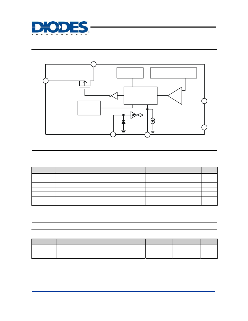
Block Diagram
Oscillation
Circuit
Reference Voltage
Source with Soft Start
PWM-Switched
Control Circuit
+
-
Vss
V
EN
EN
100uA
OCSET
FB
Vcc
Thermal
Shutdown
Output
Absolute Maximum Ratings
Symbol
Parameter
Rating
Unit
V
CC
V
CC
Pin Voltage
V
SS
- 0.3 to V
SS
+ 25
V
V
FB
Feedback Pin Voltage
V
SS
- 0.3 to V
CC
V
V
EN
EN Pin Voltage
V
SS
- 0.3 to V
IN
+ 0.3
V
V
OUT
Switch
Pin
Voltage
V
SS
- 0.3 to V
IN
+ 0.3
V
P
D
Power Dissipation
Internally limited
mW
T
OP
Operating Junction Temperature Range
-20 to +125
o
C
T
ST
Storage Temperature Range
-65 to +150
o
C
Caution: The absolute maximum ratings are rated values exceeding which the product could suffer physical damage. These values must therefore not be
exceeded under any conditions.
Recommended Operating Conditions
Symbol
Parameter
Min
Max
Unit
V
IN
Input
Voltage
3.6
23
V
I
OUT
Output
Current
0
3
A
T
A
Operating Ambient Temperature
-25
85
o
C