Data sheet, Typical performance characteristics, Electrical characteristics (continued) – Diodes AZ34063D User Manual
Page 6: Output ≥ 10, Driver - 7.0ma, 0v, t, C, unless otherwise specified.), Oscillator timing capacitor
1A STEP-DOWN/STEP-UP/INVERTING DC-DC CONVERTER AZ34063D
6
Mar. 2010 Rev. 1. 3
BCD Semiconductor Manufacturing Limited
Data Sheet
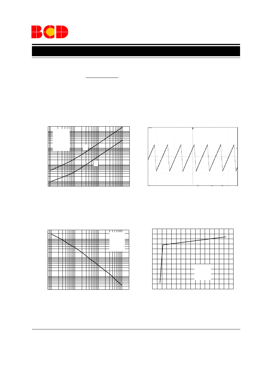
Figure 4. Output Switch On-Off Time vs.
Figure 5. Timing Capacitor Waveform
Typical Performance Characteristics
Oscillator Timing Capacitor
Time 20
µs/DIV
I
C
output
≥ 10
Forced
β of output switch:
* The 100
Ω resistor in the emitter of the driver device requires about 7.0 mA before the output switch conducts.
I
C
driver - 7.0mA*
Figure 6. Oscillator Frequency vs.Timing Capacitor
Figure 7. Standby Supply Current vs. Supply Voltage
Electrical Characteristics (Continued)
Pin 1,5,8=open
C
T
=1.0nF
T
A
=25
o
C
V
CC
=5.0V
V
PIN7
=V
CC
V
PIN2
=GND
0
5
10
15
20
25
30
35
40
0.5
1.0
1.5
2.0
2.5
3.0
3.5
C
T
=1.0nF
V
PIN7
=V
CC
V
PIN2
=GND
I
CC
Supply Curr
e
nt
(
m
A)
V
CC
Supply Voltage (V)
0.1
1
10
100
1
10
100
1000
t
off
t
on
V
CC
=5.0V
V
PIN7
=V
CC
V
PIN5
=GND
T
A
=25
O
C
To
n-
of
f Ou
tp
ut
Sw
itc
h
O
n-
O
ff
Ti
me
(
µ
s)
C
T
Oscillator Timing Capacitor (nF)
0.1
1
10
100
1
10
100
O
scill
at
o
r F
reque
ncy
(k
Hz)
C
T
Timing Capacitor (nF)
V
CC
=5.0V
V
PIN7
=V
CC
V
PIN5
=GND
T
A
=25
O
C
(
V
CC
=5.0V, T
A
=25
o
C, unless otherwise specified.)
V
o
sc Oscillat
o
r V
o
ltage (V)
2
00
m
V
/DI
V