Ap2004, Electrical characteristics, Pwm buck controller – Diodes AP2004 User Manual
Page 4
AP2004
PWM BUCK CONTROLLER
AP2004 Rev. 3
4 of 8
FEBRUARY 2009
©
Diodes Incorporated
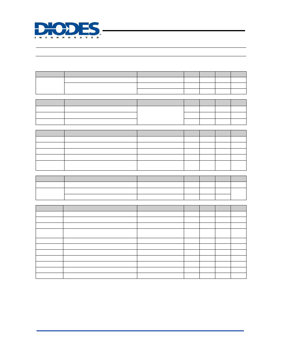
Electrical Characteristics
(T
A
= 25ºC, V
CC
= 6V, f = 200 Khz)
Reference (REF)
Symbol
Parameter
Conditions
Min
Typ.
Max
Unit
V
REF
Comp connect to FB
1.225
1.25
1.275
V
Output voltage change with
temperature
T
A
= -20ºC ~ 25ºC
-0.1
±1
%
T
A
= 25ºC ~ 85ºC
-0.2
±1
%
Under voltage lockout (UVLO)
Symbol
Parameter
Conditions
Min
Typ.
Max
Unit
V
UT
Upper threshold voltage (V
CC
)
I
O(REF)
= 0.1mA
T
A
= 25ºC
2.9 V
V
LWT
Lower threshold voltage (V
CC
)
2.4
V
V
HT
Hysteresis
(V
CC
)
500
mV
Short-circuit protection (SCP) control
Symbol
Parameter
Conditions
Min
Typ.
Max
Unit
V
IT
Input threshold voltage
T
A
= 25ºC
0.60
0.67
0.75
V
V
STB
Standby voltage
No pull up
100
130
160
mV
V
LT
Latched input voltage
No pull up
50
100
mV
I
SCP
Input (source) current
V
I
= 0.7V, T
A
= 25ºC
-10
-15
-20
µA
V
CT
Comparator threshold voltage
(COMP)
1.5
V
Oscillator (OSC)
Symbol
Parameter
Conditions
Min
Typ.
Max
Unit
F
OSC
Frequency
C
T
= 270 pF
200
KHz
ΔF
OSC
Standard deviation of frequency
C
T
= 270 pF
10
%
Frequency change with voltage
V
CC
= 3.6V ~ 20V
1
Error-amplifier
Symbol
Parameter
Conditions
Min
Typ.
Max
Unit
V
IO
Input
offset
voltage
V
O
(FB) = 1.25V
±6
mV
I
IO
Input
offset
current
V
O
(FB) = 1.25V
±100
nA
I
IB
Input bias current
V
O
(FB) = 1.25V
160
500
nA
V
CM
Common-mode input voltage range
V
CC
= 3.6V ~ 20V
1.05
1.45
V
AV
Open-loop voltage amplification
R
F
= 200 k
Ω 70
80
dB
GBW Unity-gain
bandwidth
1.5 MHz
CMRR
Common-mode rejection ratio
60
80
dB
V
OH
Max.
output
voltage
V
ref
-0.1
V
V
OL
Min. output voltage
1
V
I
OI
Output (sink) current (COMP)
V
ID
= -0.1V, V
O
= 1.25V
0.5
1.6
mA
I
OO
Output (source) current (COMP)
V
ID
= 0.1V, V
O
= 1.25V
-45
-70
µA