Ap4312, Electrical characteristics, Thermal impedance – Diodes AP4312 User Manual
Page 5
AP4312
Document number: DS36797 Rev. 1 - 2
5 of 11
January 2014
© Diodes Incorporated
AP4312
A Product Line of
Diodes Incorporated
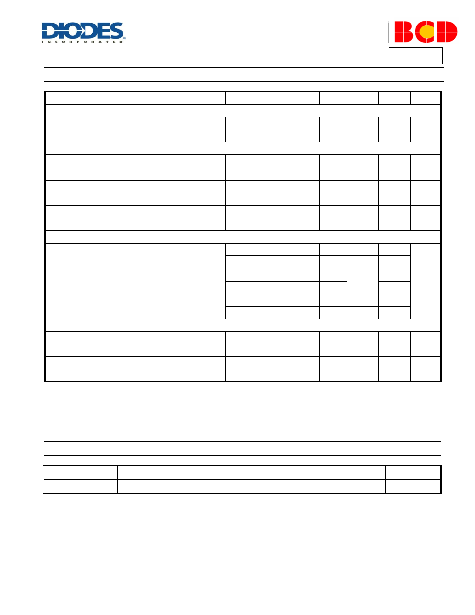
Electrical Characteristics
(@V
CC
=5V, T
A
=+25
C
, unless otherwise specified.)
Symbol
Parameters
Conditions
Min
Typ
Max
Unit
TOTAL CURRENT CONSUMPTION
I
CC
Total Supply Current Not Including the
Output Sinking Current
T
A
=+25
C
–
180
–
μA
-40
C A <+105 C – – 300 VOLTAGE CONTROL LOOP Gmv Transconductance of Voltage Control T A =+25 C 1 3.5 – mA/mV -40 C A <+105 C – 2.5 – V REF Voltage Control Loop Reference T A =+25 C 1.204 1.21 1.216 V -40 C A <+105 C 1.186 1.234 I IBV Input Bias Current (V CTRL ) T A =+25 C – 50 – nA -40 C A <+105 C – 100 – CURRENT CONTROL LOOP Gmi Transconductance of Current Control T A =+25 C 1.5 7 – mA/mV -40 C A <+105 C 1.5 7 – V SENSE Current Control Loop Reference T A =+25 C 67.9 70 72.1 mV -40 C A <+105 C 66 74 I IBI Current Out of Pin I CTRL at V SENSE T A =+25 C – 18 – μA -40 C A <+105 C – 35 – OUTPUT STAGE V OL Low Output Voltage Level T A =+25 C, I SINK =2mA – 100 – mV -40 C A <+105 C, I SINK =2mA – 100 – I OS Output Short Circuit Current. CC. Sink Current Only T A =+25 C – 27 50 mA -40 C A <+105 C – 35 – Thermal Impedance Symbol Parameter Value Unit θ JC Thermal Resistance (Junction to Case) 84 C/W
Loop Op-Amp
(Sink Current Only)
Loop Op-Amp
(Sink Current Only)
Output to V