Diodes 1N5817 - 1N5819 User Manual
Features, 0a schottky barrier rectifier, Maximum ratings and electrical characteristics
DS23001 Rev. 8 - 2
1 of 3
1N5817-1N5819
www.diodes.com
ã
Diodes Incorporated
Features
1N5817 - 1N5819
1.0A SCHOTTKY BARRIER RECTIFIER
A
A
B
C
D
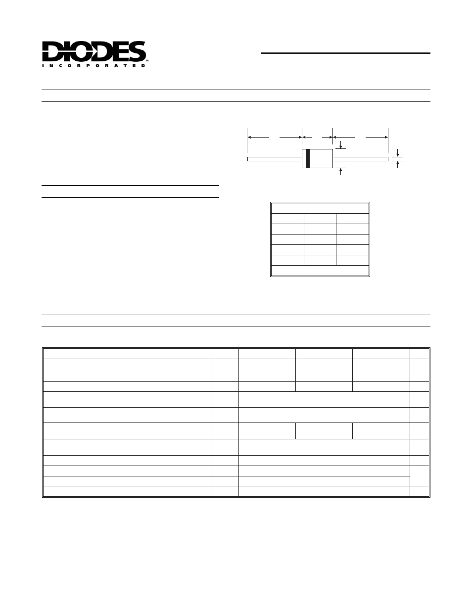
DO-41 Plastic
Dim
Min
Max
A
25.40
¾
B
4.06
5.21
C
0.71
0.864
D
2.00
2.72
All Dimensions in mm
Maximum Ratings and Electrical Characteristics
@ T
A
= 25
°
C unless otherwise specified
·
Guard Ring Die Construction for Transient Protection
·
Low Power Loss, High Efficiency
·
High Surge Capability
·
High Current Capability and Low Forward Voltage Drop
·
For Use in Low Voltage, High Frequency Inverters, Free
Wheeling, and Polarity Protection Application
·
Lead Free Finish, RoHS Compliant (Note 5)
Mechanical Data
·
Case: DO-41
·
Case Material: Molded Plastic. UL Flammability
Classification Rating 94V-0
·
Moisture Sensitivity: Level 1 per J-STD-020C
·
Terminals: Finish
¾
Tin. Plated Leads Solderable per
MIL-STD-202, Method 208
·
Polarity: Cathode Band
·
Ordering Information: See Page 2
·
Marking: Type Number and Date Code
·
Weight: 0.3 grams (approximate)
Single phase, half wave, 60Hz, resistive or inductive load.
For capacitive load, derate current by 20%.
Characteristic
Symbol
1N5817
1N5818
1N5819
Unit
Peak Repetitive Reverse Voltage
Working Peak Reverse Voltage
DC Blocking Voltage
V
RRM
V
RWM
V
R
20
30
40
V
RMS Reverse Voltage
V
R(RMS)
14
21
28
V
Average Rectified Output Current
(Note 1)
@ T
L
= 90
°
C
I
O
1.0
A
Non-Repetitive Peak Forward Surge Current 8.3ms
single half sine-wave superimposed on rated load
I
FSM
25
A
Forward Voltage (Note 2)
@ I
F
= 1.0A
@ I
F
= 3.0A
V
FM
0.450
0.750
0.550
0.875
0.60
0.90
V
Peak Reverse Leakage Current
@ T
A
= 25
°
C
at Rated DC Blocking Voltage (Note 2)
@ T
A
= 100
°
C
I
RM
1.0
10
mA
Typical Total Capacitance (Note 3)
C
T
110
pF
Typical Thermal Resistance Junction to Lead (Note 4)
R
q
JL
15
°
C/W
Typical Thermal Resistance Junction to Ambient
R
q
JA
50
Operating and Storage Temperature Range
T
j,
T
STG
-65 to +125
°
C
Notes: 1. Measured at ambient temperature at a distance of 9.5mm from the case.
2. Short duration test pulse used to minimize self-heating effect.
3. Measured at 1.0MHz and applied reverse voltage of 4.0V DC.
4. Thermal resistance from junction to lead vertical P.C.B. mounted, 0.375" (9.5mm) lead length with 1.5 x 1.5" (38 x 38mm)
copper pads.
5. RoHS revision 13.2.2003. Glass and High Temperature Solder Exemptions Applied, see
EU Directive Annex Notes 5 and 7.