Diodes ZR4040-4.1 User Manual
Description, Features, Applications
ZR4040-4.1
ZR4040-4.1
Document number: DS32171 Rev. 5 - 2
1 of 5
June 2010
© Diodes Incorporated
A Product Line of
Diodes Incorporated
PRECISION 4.1 VOLT MICROPOWER VOLTAGE REFERENCE
Description
The ZR4040-4.1 uses a bandgap circuit design to achieve a
precision micropower voltage reference of 4.1 volts. The
device is available in a small outline surface mount package,
ideal for applications where space saving is important, as
well as packages for through hole requirements.
The ZR4040-4.1 design provides a stable voltage without an
external capacitor and is stable with capacitive loads. The
ZR4040-4.1 is recommended for operation between 60
μA
and 15mA and so is ideally suited to low power and battery
powered applications.
Excellent performance is maintained to an absolute
maximum of 25mA, however the rugged design and 20 volt
processing allows the reference to withstand transient
effects and currents up to 200mA. Superior switching
capability allows the device to reach stable operating
conditions in only a few microseconds.
Features
•
Small outline SOT23 package
•
No stabilizing capacitor required
• Typical
T
C
20ppm/°C
•
Typical slope resistance 0.55
Ω
•
2% and 1% tolerance
•
Industrial temperature range
•
Operating current 60
μA to 15mA
•
“Green” molding compound (No Br, Sb)
Applications
•
Battery powered and portable equipment.
•
Metering and measurement systems.
• Instrumentation.
• Test
equipment.
•
Data acquisition systems.
•
Precision power supplies.
• Crystal
oscillators.
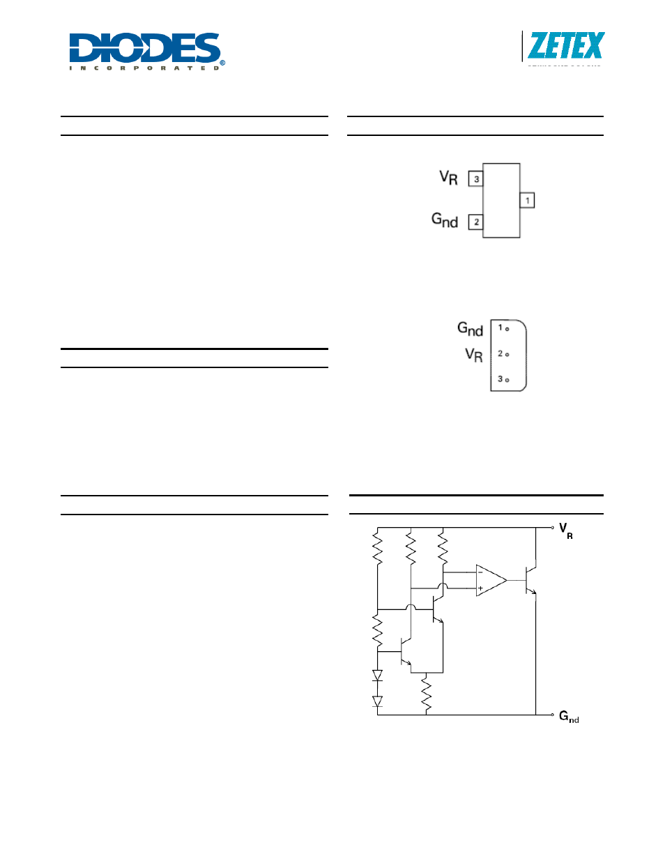
Pin Assignments
SOT23 Package Suffix - F
(Top View)
Pin 1 floating or connected to pin 2
E-Line, 3 pin, Rev Package Suffix – R
(Bottom View)
Pin 3 floating or connected to pin 1
Typical Application Circuit
OBSOLETE