Absolute maximum ratings, Recommended operating conditions, Electrical characteristics – Diodes ZMR Series User Manual
Page 2: Zmr series
ZMR Series
Document number: DS32195 Rev. 11 - 2
2 of 7
March 2013
© Diodes Incorporated
ZMR Series
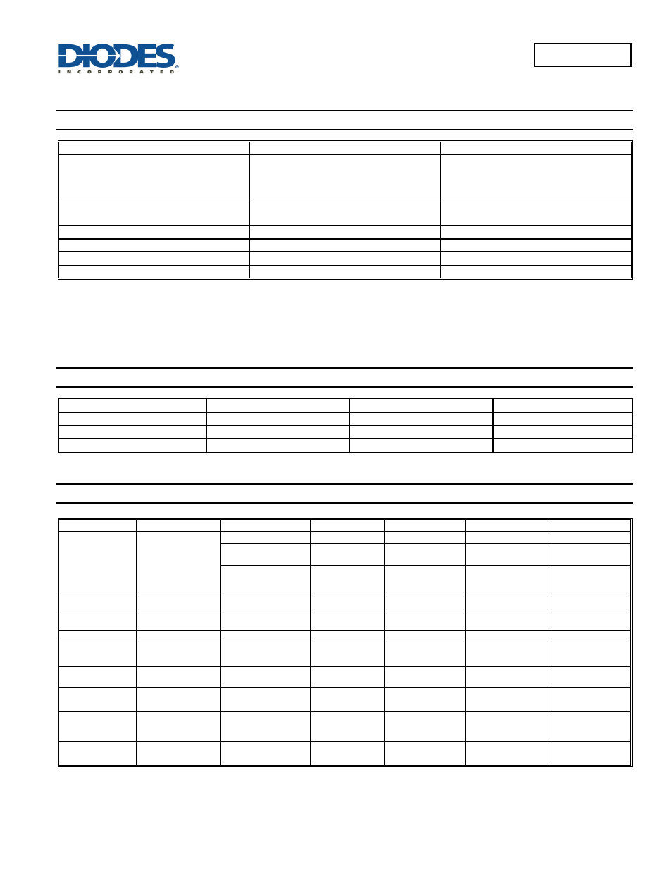
Absolute Maximum Ratings
(@T
A
= +25°C, unless otherwise specified.)
Parameter Rating
Unit
Input Voltage
ZMR250
ZMR330
ZMR500
22.5
24
25
V
Power Dissipation (T
AMB
= +25°C) (Note 6)
SOT23
500
mW
Output Current (I
O
) 100
mA
Ambient Temperature
-55 to +125
°C
Maximum Junction Temperature
125
°C
Storage Temperature
-65 to +150
°C
Notes: 4. The maximum operating input voltage and output current of the device will be governed by the maximum power dissipation of the selected package.
Maximum package power dissipation is specified at 25°C and must be linearly derated to zero at T
AMB
= +125°C.
5. The following data represents pulse test conditions with junction temperatures as indicated at the initiation of the test. Continuous operation of the
devices with the stated conditions might exceed the power dissipation limits of the chosen package.
6. Maximum power dissipation for the SOT23 package, is calculated assuming that the device is mounted on a ceramic substrate measuring
15x15x0.6mm.
Recommended Operating Conditions
(@T
A
= +25°C, unless otherwise specified.)
Electrical Characteristics
(@T
A
= +25°C, I
O
= 10mA, V
IN
= 6.5V, unless otherwise specified.)
ZMR250
Symbol Parameter Condition Min
Typ
Max
Unit
V
O
Output
Voltage
2.438
2.5
2.563
V
I
O
= 0 to 50mA
T
J
= -55°C to +125°C
2.360 2.640 V
V
IN
= 4.5 to 22.5V
I
O
= 0 to 50mA
T
J
= -55°C to +125°C
2.630 2.640 V
ΔV
O
Line
Regulation
V
IN
= 4.5 to 22.5V
5
15
mV
ΔV
O
Load
Regulation
I
O
= 0 to 50mA
I
O
= 0 to 10mA
20
12
30 mV
I
S
Supply
Current
T
J
= -55°C to +125°C
30
40
µA
ΔI
S
Supply Current
Change
I
O
= 0 to 50mA
V
IN
= 4.5 to 22.5V
1
2
±10
10
µA
V
N
Output Noise
Voltage
f = 10Hz to 10kHz
65
µVrms
ΔV
IN
/ΔV
O
Ripple
Rejection V
IN
= 6.3 to 18V
f = 120Hz
55 75
dB
V
IN
Input Voltage
Required to Maintain
Regulation
3.9
V
ΔV
O
/Δ
T
AverageTemperature
Coeffcient V
O
I
O
= 5.0mA
T
J
= -55°C to +125°C
0.275
0.700
mV/°C
Input Voltage Range
Min
Max
Unit
ZMR250 4.2
22.5
V
ZMR330 4.8
24
V
ZMR500 7.0
25
V