Application information, Zxct1020, Gnd v – Diodes ZXCT1020 User Manual
Page 11: S+ s- (load)
ZXCT1020
© Zetex Semiconductors plc 2007
Application information
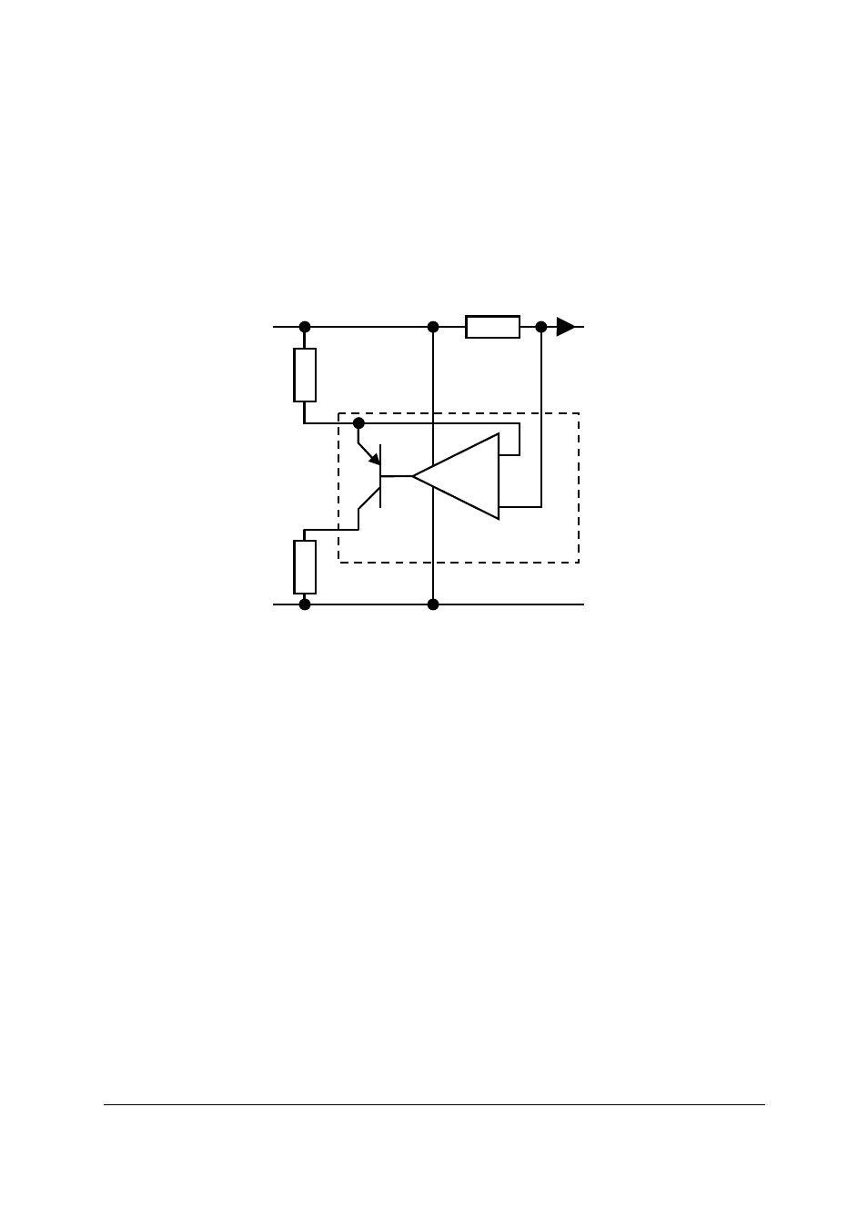
The ZXCT1020 has a V
B
pin that is used to provide power to the current monitor. The maximum
voltage applied to the ZXCT1020 must be applied to this pin. The S+ and S- pins are used to
measure the current flowing to the load through the sense resistor. In normal use, the S+ is tied
to V
B
via a shunt resistor, R
H
making the ZXCT1020 essentially line powered.
The ZXCT1020 has a programmable gain set by the ratio of two external resistors R
G
and R
SH
.
R
SH
sets the transconductance whereas R
G
set the gain and results in an output voltage defined
as:
Where V
SENSE
= R
SENSE
x I
L
The ZXCT1020 has been tested to the same conditions as the ZXCT1021 giving an overall voltage
gain of 10. The gain of the ZXCT1020 can be adjusted simply by varying R
G
. So to achieve a gain
of 50 R
G
is increased from 15k
⍀ to 75k⍀. An alternative is to decrease R
SH
from 1.5k
⍀ to 300⍀.
Decreasing R
SH
increases the transconductance and, if for any given gain, reducing the R
SH
will
reduce the overall output impedance.
To achieve a gain of 100, for example, the following resistor values could be used:
R
SH
= 150 R
G
= 15k
S+
S-
(LOAD)
V
B
I
L
R
SH
R
S
GND
V
OUT
5
4
-
+
1
ZXCT1020
2
3
R
G
V
OUT
R
G
R
SH
----------
V
SENSE
Ч
=