Zxct1051, Application information, Basic operation – Diodes ZXCT1051 User Manual
Page 7
ZXCT1051
© Zetex Semiconductors plc 2006
Application information
The ZXCT1051 is Zetex’ first current monitor with a separate power supply pin. All biasing for the
internal amplifiers comes from its separate V
CC
input and is not ‘line powered’, unlike the
ZXCT1021.
This means that at very small sense voltages the ZXCT1051 draws very little current (<1µA) from
the lines being sensed.
The separate V
CC
pin enables the ZXCT1051 to be operated at sense line voltages down to 0V,
where the ZXCT1021 would switch off. This feature enables the ZXCT1051 to be used to sense the
currents flowing through lines that have been shorted to ground and is Zetex’ first current
monitor to do this.
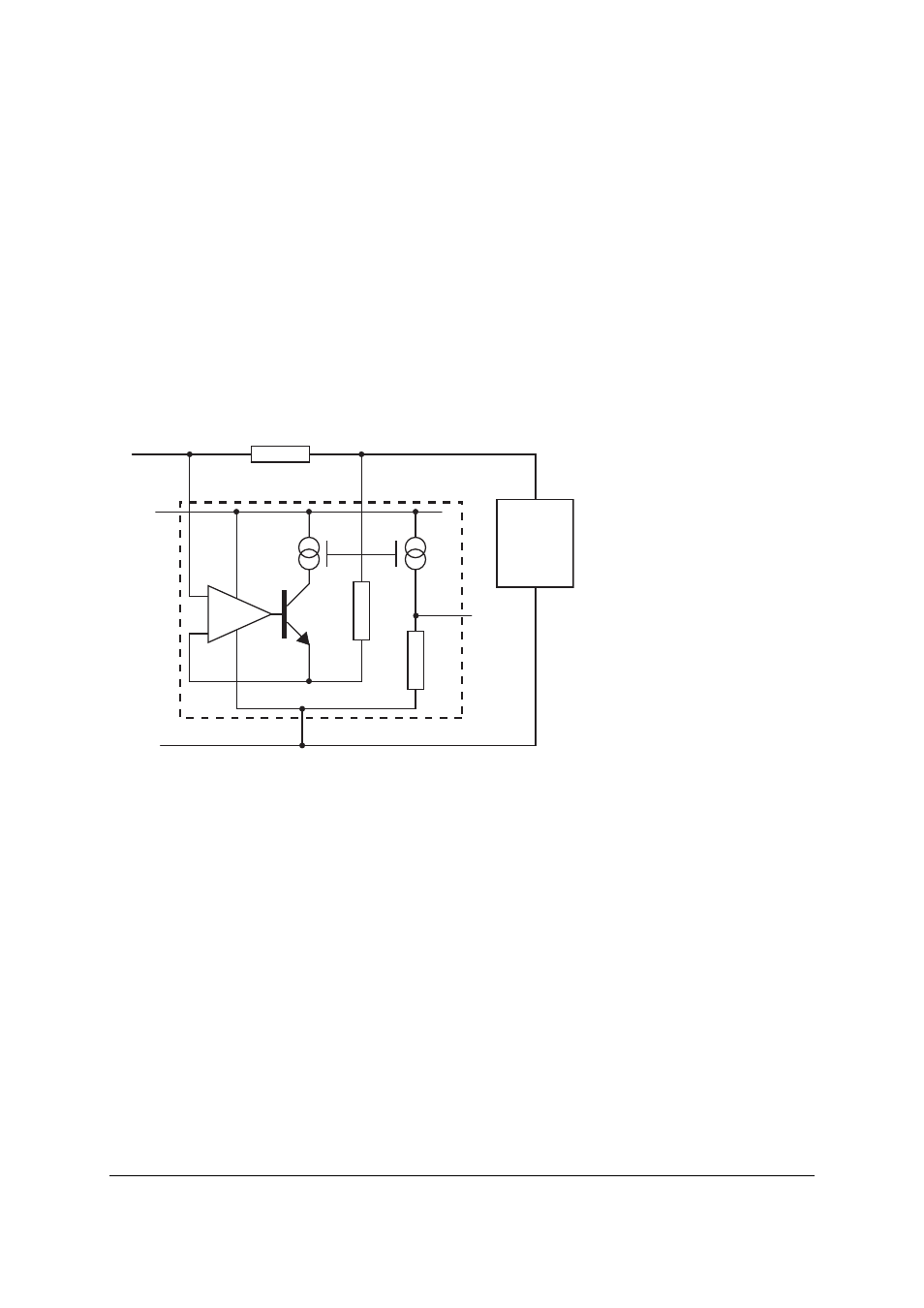
Basic operation
Load current from V
IN
is drawn through R
SENSE
developing a voltage V
SENSE
across the
ZXCT1051.
The internal amplifier forces V
SENSE
across internal resistance R
SH
causing a current to flow
through transistor Q1. This current is then converted to a voltage by R
G
. A ratio of 10:1 between
R
SH
and R
G
creates the fixed gain of 10 with an output impedance equal to R
G
(see electrical
characteristics for output current-voltage characteristics).
The gain equation of the ZXCT1051 is:
The maximum differential input voltage, V
SENSE
, is 150mV (I
L
* R
SENSE
); however voltages up to
500mV will not damage it. This can be increased further by the inclusion of a resistor, R
LIM
,
between V
SENSE
- pin and the load.
For best performance R
SENSE
should be connected as close to the V
SENSE
+ and V
SENSE
- pins thus
minimizing any series resistance with R
SENSE
.
R
SENSE
V
SENSE+
V
SENSE-
V
OUT
V
CC
V
RAIL
R
G
R
SH
Q1
GND
GND
Load
V
SENSE
I
L
R
SENSE
R
G
R
SH
-----------
1
Ч
=