Zxct1023, Micropower fixed gain of 50 current monitor, Pin descriptions – Diodes ZXCT1023 User Manual
Page 2: Absolute maximum ratings, Recommended operating conditions
ZXCT1023
MICROPOWER FIXED GAIN OF 50 CURRENT MONITOR
ZXCT1023
Document number: DS31997 Rev. 3 - 2
2 of 8
June 2011
© Diodes Incorporated
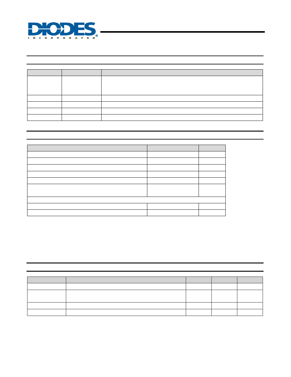
Pin Descriptions
Pin Name
Pin Number
Description
1 OUT
Voltage output. The output voltage is referenced to GND.
The overall voltage gain is 50, i.e.,
V
OUT
= 50 x V
SENSE
where V
SENSE
= V
S+
- V
S-
2
GND
Ground and substrate connection of device
3
S-
High impedence negative sense voltage input
4
S+
Positive sense input. Also acts as power supply pin to ZXCT1023
Central Paddle
Substrate. Connect to GND
Absolute Maximum Ratings
Description
Rating
Unit
Voltage on S+ (Note 1)
-0.5 to 20
V
Voltage on S- (Note 1, 2), OUT(Note 1)
-0.5 V
S+
+0.5
V
V
SENSE
(Note 3)
-0.5 to +2.5
V
Junction Temperature
-40 to 125
°C
Storage Temperature
-55 to 150
°C
Package Power Dissipation (T
A
= 25°C)
TDFN1218
mW
ESD Ratings
Human Body Model
2000
V
Machine Model
150
V
These are stress ratings only. Operation outside the absolute maximum ratings may cause device failure. Operation at the absolute
maximum rating for extended periods may reduce device reliability.
Semiconductor devices are ESD sensitive and may be damaged by exposure to ESD events. Suitable ESD precautions should be taken
when handling and transporting these devices.
Notes:
1. Measured with respect to GND pin
2. Subject to absolute maximum V
SENSE
not being exceeded.
3.
V
SENSE
is defined as the voltage difference across the sense resistor, R
S
.
4. The usable V
SENSE
range is limited by the output voltage range; and as such will be reduced at lower V
S+
values.
Recommended Operating Conditions
(T
A
= 25
°C)
Symbol
Parameter
Min
Max
Unit
V
S+
(Note 1)
Common-Mode Sense Input Range
2.5
20
V
V
SENSE
Differential Sense Input Voltage Range
0
380
(Note 4)
mV
V
OUT
Output Voltage Range
0
V
S-
- 1
V
T
A
Ambient Temperature Range
-40
85
°C