Zxct1030, Voltage output current monitor – Diodes ZXCT1030 User Manual
Page 5
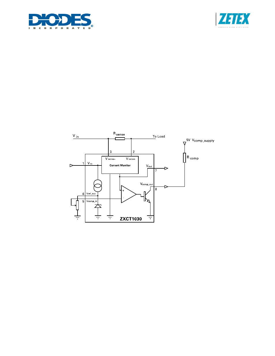
ZXCT1030
ZXCT1030
Document number: DS32161 Rev. 4 - 2
5 of 7
June 2010
© Diodes Incorporated
A Product Line of
Diodes Incorporated
Voltage output current monitor
Referring to the block diagram, the current monitor takes the small voltage developed across the sense resistor (V
SENSE
)
and transfers it from the large common mode supply voltage to a ground referenced signal with a gain of 10. The sense
input common mode range is 2.2V to 20V. In this range, a linear output voltage is delivered.
Reference
The bandgap reference allows the comparator to compare the translated V
SENSE
with threshold value chosen by the user
which can be any voltage from 0 to 1.24V, configured by two external resistors which forms V
COMP
_
IN
.
The output current which can be drawn from the comparator reference (I
REF
source) is limited to 5
μA, making
potentiometers
≥250kΩ suitable for setting a threshold level. Where a lower potentiometer resistor value is used, an
additional resistor value should be inserted between V
REF
and V
CC
to maintain sufficient current for the reference.
(as shown in Figure 1).
Figure 1: External Resistor for Reference Level
The voltage reference has a maximum current sink capability. This magnitude of current will be influenced by the value of
R1 which is inserted between V
REF
and V
CC
. The value of current flowing through R1 can be expressed as:
I = (V
CC
-V
REF
) / R1
Comparator
The open collector output is active low and is asserted when V
SENSE
x 10 (V
OUT
) > V
COMP
_
IN
. It can be connected to any
voltage rail up to V
IN
via a pull-up resistor. Suggest values for the resistor are in the range of 10-100k
Ω.
In the case where high load currents or a short circuit occurs, thus reducing the common mode signals (V+, V-) typically
below 2.2V, the comparator will default to the asserted state. This can eliminate a closed loop system 'latch-up' condition,
allowing the controller to remove the applied power.
Stability
To ensure stable operation of the ZXCT1030, it is recommended a decoupling capacitor is placed
across the V
CC
and
ground connections. A ceramic 10µF will be adequate.