Zldo500, Applications, 3). logic controlled power supply – Diodes ZLDO500 User Manual
Page 7: 4). over temperature shutdown
voltage of the ZLDO500 allows this circuit
technique to be implemented very effectively,
giving a highly stable and accurate low noise
supply.
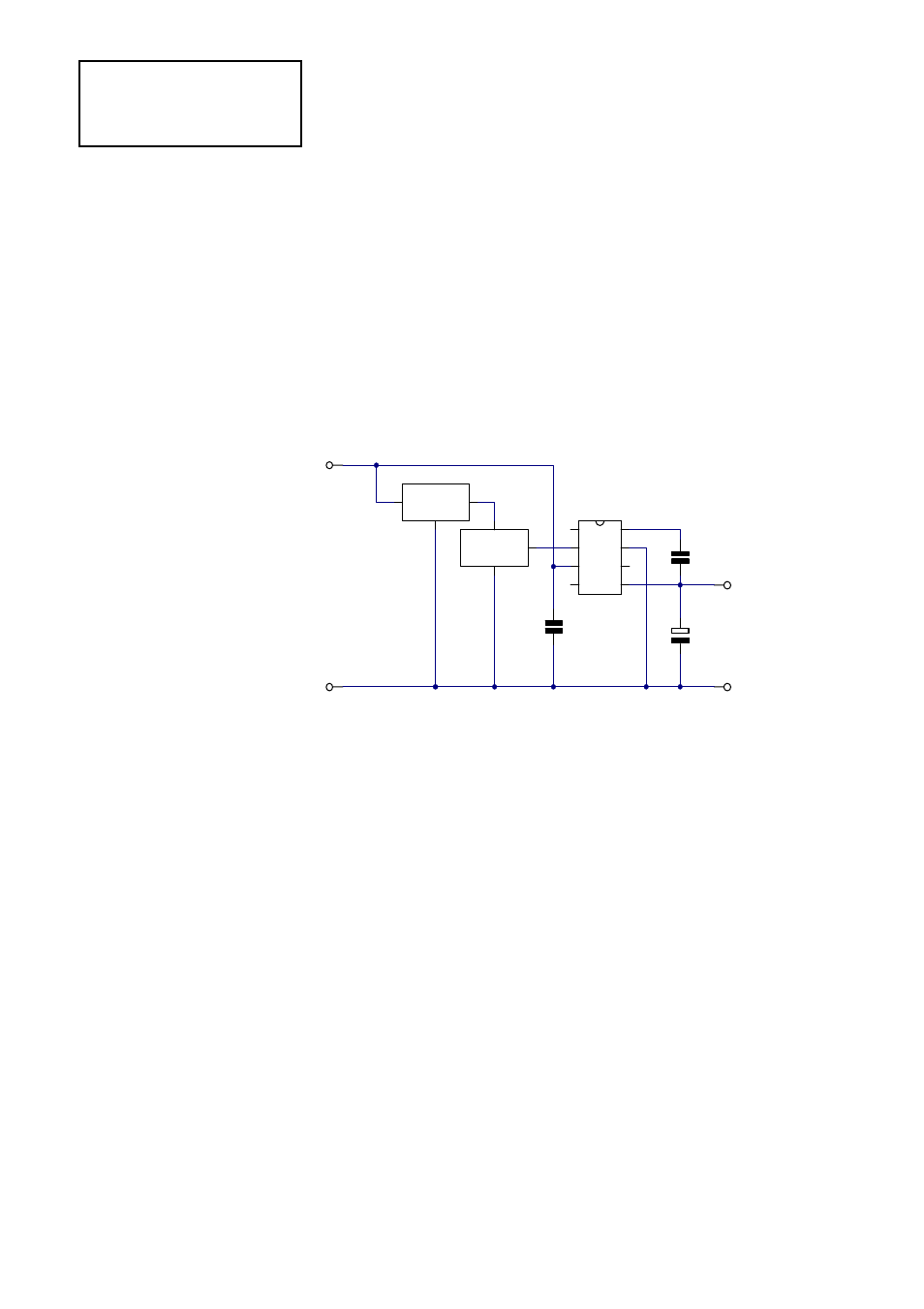
3). Logic Controlled Power Supply
Figure 3 shows all that is necessary to allow
a microprocessor to control a power supply
based on the ZLDO500 The Shutdown Control
pin (pin 2), is a logic compatible input that
disables the regulator when a voltage in
excess of 1.5V is applied. The current required
to drive this input is less than 10
µ
A. When the
regulator is shutdown in this way, the
quiescent current of the ZLDO500 falls to
around 11
µ
A. This makes the regulator
suitable for a wide range of battery powered
applications where intermittent operation
occurs. The shutdown control pin should not
be taken to a voltage higher than Vin if low
quiescent supply current is important. The
shutdown control is a high impedance input
and so if not required, should be wired to the
ground pin (pin 7).
4). Over Temperature Shutdown
The ZLDO500 regulator includes an over
temperature shutdown circuit that disables
the regulator if its chip temperature should
exceed 125°C for any reason. Although
intended to provide a limited guard against
excessive internal power dissipation, this
circuit will shut down the regulator if its
ambient rises above 125°C. Thus, the
regulator could be used to disable a circuit in
the event of the ambient temperature within
which the circuit is mounted becoming too
high. Any internal power dissipation caused
as a result of supplying load current, will
reduce the ambient temperature at which
shutdown occurs. Note that to achieve the
extremely low dropout voltage and high
current performance provided by the
ZLDO500
APPLICATIONS
Spg
D/C
Vout
LBF
SC
Vin
N/C
Gnd
IC2
ZLDO500
C2
1uF
C1
10pF
C3
100nF
0V
+5V
Microproc.
System
Supply Input
Vin Vout
Gnd
IC1
ZSR500
0V
+6.7V
to 20V
Figure 3
4-86