Diodes ZTX603 User Manual
Diodes Hardware
NPN SILICON PLANAR MEDIUM POWER
DARLINGTON TRANSISTORS
ISSUE 1 MARCH 94
FEATURES
* 80 Volt V
CEO
* 1 Amp continuous current
* Gain of 2K at I
C
=1 Amp
* P
tot
= 1 Watt
ABSOLUTE MAXIMUM RATINGS.
PARAMETER
SYMBOL
ZTX602
ZTX603
UNIT
Collector-Base Voltage
V
CBO
80
100
V
Collector-Emitter Voltage
V
CEO
60
80
V
Emitter-Base Voltage
V
EBO
10
V
Peak Pulse Current
I
CM
4
A
Continuous Collector Current
I
C
1
A
Power Dissipation at T
amb
= 25°C
derate above 25°C
P
tot
1
5.7
W
mW/ °C
Operating and Storage Temperature Range
T
j
:T
stg
-55 to +200
°C
ELECTRICAL CHARACTERISTICS (at T
amb
= 25°C unless otherwise stated).
PARAMETER
SYMBOL
ZTX602
ZTX603
UNIT CONDITIONS.
MIN.
MAX. MIN.
MAX.
Collector-Base
Breakdown Voltage
V
(BR)CBO
80
100
V
I
C
=100
µ
A
Collector-Emitter
Breakdown Voltage
V
(BR)CEO
60
80
V
I
C
=10mA*
Emitter-Base
Breakdown Voltage
V
(BR)EBO
10
10
V
I
E
=100
µ
A
Collector Cut-Off
Current
I
CBO
0.01
10
0.01
10
µ
A
µ
A
µ
A
µ
A
V
CB
=60V
V
CB
=80V
V
CB
=60V,
T
amb
=100°C
V
CB
=80V,
T
amb
=100°C
Emitter Cut-Off
Current
I
EBO
0.1
0.1
µ
A
V
EB
=8V
Colllector-Emitter
Cut-Off Current
I
CES
10
10
µ
A
µ
A
V
CES
=60V
V
CES
=80V
Collector-Emitter
Saturation Voltage
V
CE(sat)
1.0
1.0
1.0
1.0
V
V
I
C
=400mA,
I
B
=0.4mA*
I
C
=1A, I
B
=1mA*
Base-Emitter
Saturation Voltage
V
BE(sat)
1.8
1.8
V
I
C
=1A, I
B
=1mA*
Base-Emitter
Turn-On Voltage
V
BE(on)
1.7
1.7
V
IC=1A, V
CE
=5V*
E-Line
TO92 Compatible
ZTX602
ZTX603
3-209
ELECTRICAL CHARACTERISTICS (at T
amb
= 25°C unless otherwise stated).
PARAMETER
SYMBOL
ZTX602
ZTX603
UNIT CONDITIONS.
MIN.
MAX. MIN.
MAX.
Static Forward
Current Transfer
Ratio
h
FE
2K
5K
2K
0.5K
100K
2K
5K
2K
0.5K
100K
I
C
=50mA, V
CE
=5V
I
C
=500mA, V
CE
=5V*
I
C
=1A, V
CE
=5V*
I
C
=2A, V
CE
=5V*
Transition Frequency f
T
150
150
MHz
I
C
=100mA, V
CE
=10V
f=20MHz
Input Capacitance
C
ibo
90 Typical
pF
V
EB
=500mV, f=1MHz
Output Capacitance
C
obo
15 Typical
pF
V
CB
=10V, f=1MHz
Switching Times
t
on
0.5 Typical
µ
s
I
C
=500mA, V
CE
=10V
I
B1
=I
B2
=0.5mA
t
off
1.1 Typical
µ
s
*Measured under pulsed conditions. Pulse width=300
µ
s. Duty cycle
≤
2%
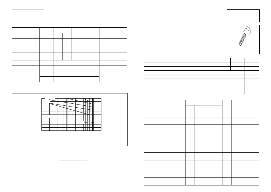
The maximum permissible operational temperature can be obtained from this graph using
the following equation
T
amb
(
max
)
=
Power
(
max
)
−
Power
(
act
)
0.0057
+
25°
C
T
amb(max )
= Maximum operating ambient temperature
Power(max) = Maximum power dissipation figure, obtained from the above graph for a
given V
CE
and source resistance (R
S
)
Power(actual)= Actual power dissipation in users circuit
ZTX602
ZTX603
C
B
E
Voltage Derating Graph
V
CE
- Collector-Emitter Voltage (Volts)
1.0
0.8
0.6
0.4
0
0.2
R
5
= 50K
Ω
1
10
100
DC Conditions
R
5
= 200K
Ω
R
5
=
∞
Maxim
um
Powe
r Dissi
pa
tion
(W
)
200
R
5
= 1M
Ω
R
5
= 10K
Ω
ZTX603
ZTX602
3-210