Electrical characteristics, Zxt951k, A product line of diodes incorporated – Diodes ZXT951K User Manual
Page 4
ZXT951K
Document number: DS33642 Rev. 3 - 2
4 of 7
August 2012
© Diodes Incorporated
A Product Line of
Diodes Incorporated
ZXT951K
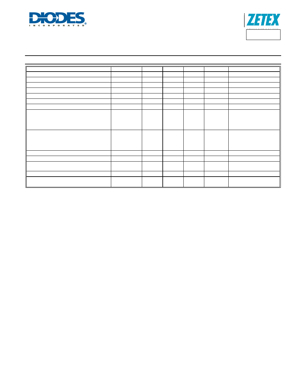
Electrical Characteristics
(@T
A
= +25°C, unless otherwise specified.)
Characteristic Symbol
Min
Typ.
Max
Unit
Test
Condition
Collector-Base Breakdown Voltage
BV
CBO
-100 -125 -
V I
C
= -100µA
Collector-Base Breakdown Voltage
BV
CER
-100 -125 -
V I
C
= -100µA, R
BE
≤1kΩ
Collector-Emitter Breakdown Voltage (Note 9)
BV
CEO
-60 -80 -
V
I
C
= -10mA
Emitter-Base Breakdown Voltage
BV
EBO
-7 -8.1 -
V
I
E
= -100µA
Collector Cutoff Current
I
CBO
- <1
-20 nA
V
CB
= -80V
Emitter Cutoff Current
I
EBO
-
<1
-10 nA
V
EB
= -6V
Emitter Cutoff Current
I
CER
-
<1
-20 nA
V
CE
= -80V, R
BE
≤1kΩ
DC current transfer Static ratio (Note 9)
h
FE
100
100
50
15
230
200
110
40
-
300
-
-
-
I
C
= -10mA, V
CE
= -1V
I
C
= -2A, V
CE
= -1V
I
C
= -6A, V
CE
= -1V
I
C
= -10A, V
CE
= -1V
Collector-Emitter Saturation Voltage (Note 9)
V
CE(sat)
-
-
-
-
-13
-60
-115
-315
-25
-90
-165
-400
mV
I
C
= -0.1A, I
B
= -10mA
I
C
= -1A, I
B
= -100mA
I
C
= -2A, I
B
= -200mA
I
C
= -6A, I
B
= -600mA
Base-Emitter Saturation Voltage (Note 9)
V
BE(sat)
- -1.05
-1.2 V
I
C
= -6A, I
B
= -600mA
Base-Emitter Turn-on Voltage (Note 9)
V
BE(on)
- -0.92
-1.05 V
I
C
= -6A, V
CE
= -1V
Transitional Frequency
f
T
- 120 - MHz
I
C
= -100mA, V
CE
= -10V
f = 50MHz
Output capacitance
C
OBO
- 74 - pF
V
CB
= -10V, f = 1MHz,
Switching times
t
ON
t
OFF
-
82
350
- nS
I
C
= -2A, V
CC
= -10V,
I
B1
= I
B2
= -200mA
Notes:
9. Measured under pulsed conditions. Pulse width
≤ 300μs. Duty cycle ≤2%.