Zdt1048, Electrical characteristics (at t, 25°c unless otherwise stated) – Diodes ZDT1048 User Manual
Page 3
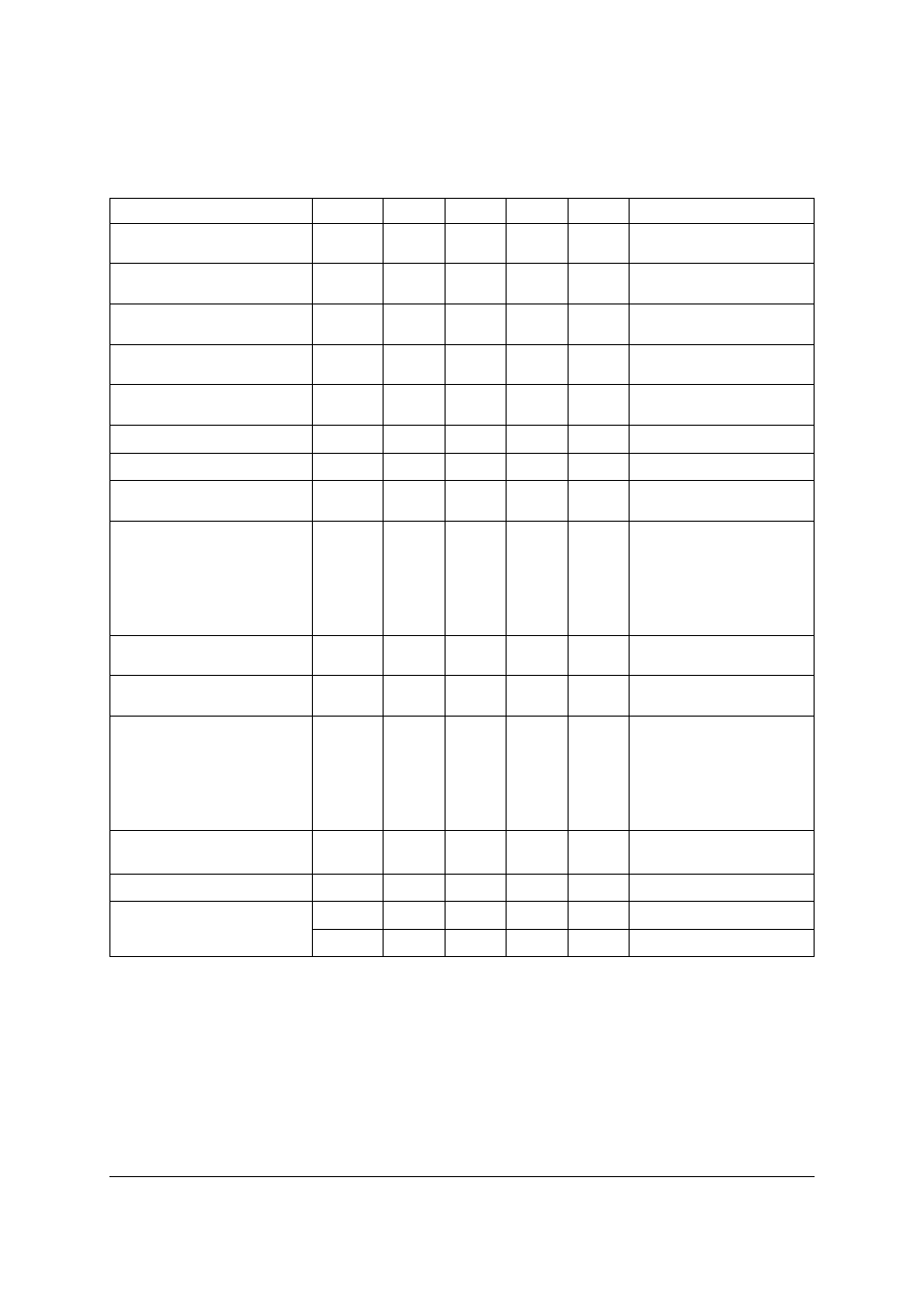
ZDT1048
Issue 2 - December 2007
3
www.zetex.com
© Zetex Semiconductors plc 2007
Electrical characteristics (at T
amb
= 25°C unless otherwise stated).
Parameter Symbol
Min.
Typ.
Max.
Unit
Conditions
Collector-base breakdown
voltage
V
(BR)CBO
50 85
V
I
C
=100µA
Collector-emitter
breakdown voltage
V
CES
50 85
V
I
C
=100µA
Collector-emitter
breakdown voltage
V
CEO
17.5 24
V
I
C
=10mA
Collector-emitter
breakdown voltage
V
CEV
50
85
V
I
C
=100µA, V
EB
=1V
Emitter-base breakdown
voltage
V
(BR)EBO
5
8.7
V
I
E
=100µA
Collector cut-off current
I
CBO
0.3
10 nA
V
CB
=35V
Emitter cut-off current
I
EBO
0.3
10 nA
V
EB
=4V
Collector-emitter cut-off
current
I
CES
0.3
10 nA
I
CES
=35V
Collector-emitter
saturation voltage
V
CE(sat)
27
55
120
200
200
45
75
160
240
300
mV
mV
mV
mV
mV
I
C
=0.5A, I
B
=10mA
(*)
I
C
=1A, I
B
=10mA
(*)
I
C
=2A, I
B
=10mA
(*)
I
C
=5A, I
B
=100mA
(*)
I
C
=5A, I
B
=50mA
(*)
NOTES:
(*) Measured under pulsed conditions. Pulse width=300µs. Duty cycle
≤ 2%
Base-emitter saturation
voltage
V
BE(sat)
1000
1100
mV
I
C
=5A, I
B
=100mA
(*)
Base-emitter turn on
voltage
V
BE(on)
900
1000
mV
I
C
=5A, V
CE
=2V
(*)
Static forward
current transfer
ratio
h
FE
280
300
300
250
50
440
450
450
300
80
1200
I
C
=10mA, V
CE
=2V
(*)
I
C
=0.5A, V
CE
=2V
(*)
I
C
=1A, V
CE
=2V
(*)
I
C
=5A, V
CE
=2V
(*)
I
C
=20A, V
CE
=2V
(*)
Transition frequency
f
T
150
MHz
I
C
=50mA, V
CE
=10V
f=50MHz
Output capacitance
C
obo
60
80
pF
V
CB
=10V, f=1MHz
Switching times
t
on
120
ns
I
C
=4A, I
B
=40mA,V
CC
=10V
t
off
250
ns
I
C
=4A, I
B
=±40mA,V
CC
=10V