Udz3v6b-udz15b, Thermal characteristics, Electrical characteristics – Diodes UDZ3V6B-UDZ15B User Manual
Page 2
UDZ3V6B-UDZ15B
Document number: DS30290 Rev. 15 - 2
2 of 5
December 2013
© Diodes Incorporated
UDZ3V6B-UDZ15B
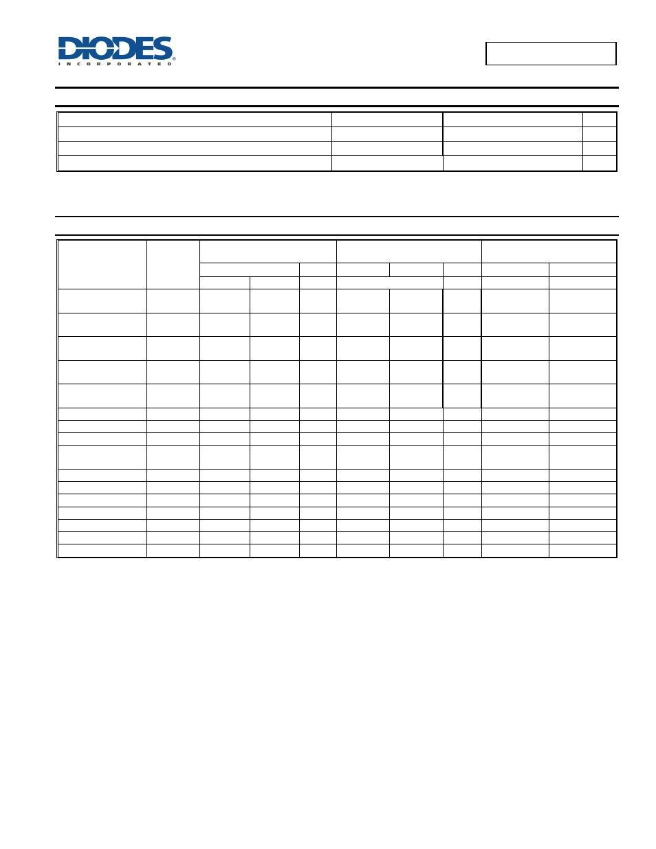
Thermal Characteristics
Characteristic
Symbol Value
Unit
Power Dissipation (Note 6)
P
D
200 mW
Thermal Resistance Junction to Ambient Air (Note 6)
R
JA
625
C/W
Operating and Storage Temperature Range
T
J,
T
STG
-65 to +150
C
Electrical Characteristics
(@T
A
= +25°C, unless otherwise specified.)
Type
Number
Marking
Code
Zener Voltage Range
(Note 7)
Maximum Zener Impedance
(Note 8)
Maximum Reverse Current
(Note 7)
V
ZT @
I
ZT
I
ZT
Z
ZT
@
I
ZT
Z
ZK
@ I
ZK
I
ZK
I
R
V
R
Min (V)
Max (V)
mA
Ω
mA
uA
V
UDZ3V6B
(Note 9)
B7 3.600 3.845 5 100 1000 1.0
10
1.0
UDZ3V9B
(Note 9)
B8 3.890 4.160 5 100 1000 1.0
5
1.0
UDZ4V3B
(Note 9)
B9 4.170 4.430 5 100 1000 1.0
5
1.0
UDZ4V7B
(Note 9)
BA 4.550
4.750 5 100 800 0.5
2
1.0
UDZ5V1B
(Note 9)
BB 4.980
5.200 5 80 500 0.5
2
1.5
UDZ5V6B
BC
5.490
5.730
5
60
200
0.5
1
2.5
UDZ6V2B
BD
6.060
6.330
5
60
100
0.5
1
3.0
UDZ6V8B
BE
6.650
6.930
5
40
60
0.5
0.5
3.5
UDZ7V5B
(Note 9)
BF
7.280
7.600
5
30
60
0.5
0.5
4.0
UDZ8V2B
BG
8.020
8.360
5
30
60
0.5
0.5
5.0
UDZ9V1B
BH
8.850
9.230
5
30
60
0.5
0.5
6.0
UDZ10B
BI
9.770
10.210
5
30
60
0.5
0.1
7.0
UDZ11B
BJ
10.760
11.220
5
30
60
0.5
0.1
8.0
UDZ12B
BK
11.740
12.240
5
30
80
0.5
0.1
9.0
UDZ13B
BL
12.910
13.490
5
37
80
0.5
0.1
10.0
UDZ15B
BM
14.340
14.980
5
42
80
0.5
0.1
11.0
Notes:
6. Part mounted on FR-4 PC board with recommended pad layout, which can be found on our website at
7. Short duration pulse test used to minimize self-heating effect.
8. The Zener impedances (Z
ZT
, Z
ZK
) are measured by superimposing a minute alternating current on the regulated current (IZ).
9. AEC-Q101 qualified