Diodes SDM20N40A User Manual
Sdm20n40a, New p roduct, Dual surface mount schottky barrier diode
Lead-free Green
DS30542 Rev. 7 - 2
1 of 3
SDM20N40A
www.diodes.com
ã
Diodes Incorporated
SDM20N40A
DUAL SURFACE MOUNT SCHOTTKY BARRIER DIODE
·
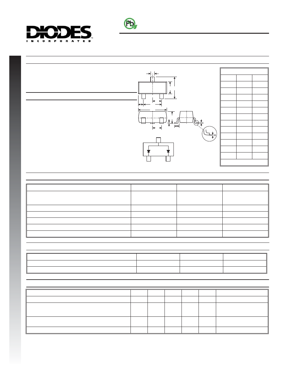
Case: SOT-23
·
Case Material: Molded Plastic. "Green" Molding
Compound. UL Flammability Classification Rating 94V-0
·
Moisture sensitivity: Level 1 per J-STD-020C
·
Terminal Connections: See Diagram
·
Terminals: Finish - Matte Tin annealed over Alloy 42
leadframe. Solderable per MIL-STD-202, Method 208
·
Marking & Type Code Information: See Last Page
·
Ordering Information: See Last Page
·
Weight: 0.008 grams (approx.)
Mechanical Data
A
E
J
L
TOP VIEW
M
B
C
H
G
D
D
K
Features
Maximum Ratings
@ T
A
= 25
°C unless otherwise specified
Notes:
1. Mounted on FR4 PC Board with recommended pad layout which can be found on our website
at
2. Short duration test pulse used to minimize self-heating effect.
3. No purposefully added lead.
4. Diodes Inc.
Electrical Characteristics
@ T
A
= 25
°C unless otherwise specified
·
Low Forward Voltage Drop
·
Common Anode Configuration
·
Lead Free By Design/RoHS Compliant (Note 3)
·
"Green" Device (Note 4)
Characteristic
Symbol
Value
Unit
Peak Repetitive Reverse Voltage
Working Peak Reverse Voltage
DC Blocking Voltage
V
RRM
V
RWM
V
R
40
V
RMS Reverse Voltage
V
R(RMS)
28
V
Forward Continuous Current, Per Element
I
FM
200
mA
Non-Repetitive Peak Forward Surge Current @ t = 8.3ms
I
FSM
1
A
Junction Temperature Range
T
j
-65 to +125
°C
Storage Temperature Range
T
STG
-65 to +150
°C
Characteristic
Symbol
Min
Typ
Max
Unit
Test Condition
Reverse Breakdown Voltage (Note 2)
V
(BR)R
40
¾
¾
V
I
R
= 500
mA
Forward Voltage (Note 2)
V
F
¾
¾
¾
¾
¾
¾
300
420
550
mV
I
F
= 10mA
I
F
= 100mA
I
F
= 200mA
Leakage Current (Note 2)
I
R
¾
¾
¾
¾
15
3
mA
mA
V
R
= 30V
V
R
= 30V, T
j
= 100°C
Total Capacitance
C
T
¾
23
50
pF
V
R
= 0V, f = 1.0MHz
NEW
P
RODUCT
TOP VIEW
SOT-23
Dim
Min
Max
A
0.37
0.51
B
1.20
1.40
C
2.30
2.50
D
0.89
1.03
E
0.45
0.60
G
1.78
2.05
H
2.80
3.00
J
0.013
0.10
K
0.903
1.10
L
0.45
0.61
M
0.085
0.180
a
0
°
8
°
All Dimensions in mm
Thermal Characteristics
@ T
A
= 25
°C unless otherwise specified
Characteristic
Symbol
Value
Unit
Power Dissipation (Note 1)
P
d
200
mW
Thermal Resistance, Junction to Ambient Air (Note 1)
R
qJA
500
°C/W