Diodes RH02 - RH06 User Manual
Rh02 - rh06, Mechanical data, Maximum ratings and electrical characteristics
Characteristic
Symbol
RH02
RH04
RH06
Unit
Peak Repetitive Reverse Voltage
Working Peak Reverse Voltage
DC Blocking Voltage
V
RMM
V
RWM
V
DC
200
400
600
V
RMS Reverse Voltage
V
RMS
140
280
420
V
Average Forward Rectified Current (Note 1) T
A
= @ 40
°C
I
O
0.5
A
Non-Repetitive Peak Forward Surge Current, 8.3 ms
Single half-sine-wave Superimposed on Rated Load
(JEDEC method)
I
FSM
30
A
Instantaneous Voltage Drop @ 0.4A (per element)
V
F
1.15
V
Peak Reverse Current at Rated
@ T
A
= 25
°C
DC Blocking Voltage (per element)
@ T
A
= 125
°C
I
R
5.0
100
mA
Maximum Reverse Recovery Time
(Note 3)
t
rr
150
250
ns
Typical Junction Capacitance (per element)
(Note 2)
C
j
13.0
pF
Typical Thermal Resistance, Junction to Ambient (Note 1)
R
qJA
85
K/W
Operating and Storage Temperature Range
T
j
, T
STG
-55 to +150
°C
DS30137 Rev. 6 - 2
1 of 3
RH02 - RH06
www.diodes.com
ã
Diodes Incorporated
RH02 - RH06
0.5A SURFACE MOUNT GLASS PASSIVATED FAST
RECOVERY BRIDGE RECTIFIER
Features
·
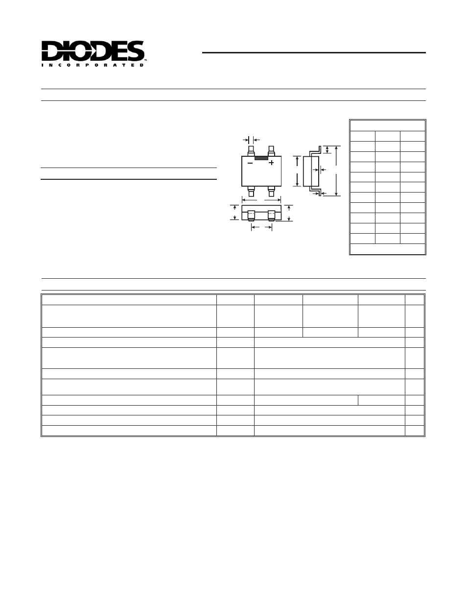
Case: MiniDIP
·
Case Material: Molded Plastic. UL Flammability
Classification Rating 94V-0
·
Terminals: Finish
¾ Bright Tin. Plated Leads, Solderable
per MIL-STD-202, Method 208
·
Polarity: As Marked on Case
·
Marking: Type Number
·
Weight: 0.125 grams (approx.)
Mechanical Data
Notes:
1. Mounted on Glass Epoxy PC Board.
2. Measured at 1.0 MHz and Applied Reverse Voltage of 4.0 V.
3. t
rr
test conditions: I
F
= 0.5A, I
R
= 1.0A, I
rr
= 0.25A.
4. RoHS revision 13.2.2003. Glass and High Temperature Solder Exemptions Applied, see
·
Glass Passivated Die Construction
·
Low Forward Voltage Drop
·
Surge Overload Rating to 30A Peak
·
Ideally Suited for Automatic Assembly
·
Miniature Package Saves Space on PC Boards
·
Lead Free Finish, RoHS Compliant (Note 4)
Maximum Ratings and Electrical Characteristics
@ T
A
= 25
°C unless otherwise specified
B
C
D E
G
H
J
F
L
K
MiniDIP
Dim
Min
Max
B
3.6
4.0
C
0.15
0.35
D
¾
0.20
E
¾
7.0
F
¾
3.00
G
0.70
1.10
H
4.5
4.9
J
2.3
2.7
K
2.3
2.7
L
0.50
0.80
All Dimensions in mm