Diodes UF2001 - UF2007 User Manual
Features, Mechanical data, Maximum ratings and electrical characteristics
UF2001 - UF2007
2.0A ULTRA-FAST RECTIFIER
Features
•
Diffused Junction
•
Ultra-Fast Switching for High Efficiency
•
Surge Overload Rating to 60A Peak
•
Low Reverse Leakage Current
•
Lead Free Finish, RoHS Compliant (Note 4)
Mechanical Data
•
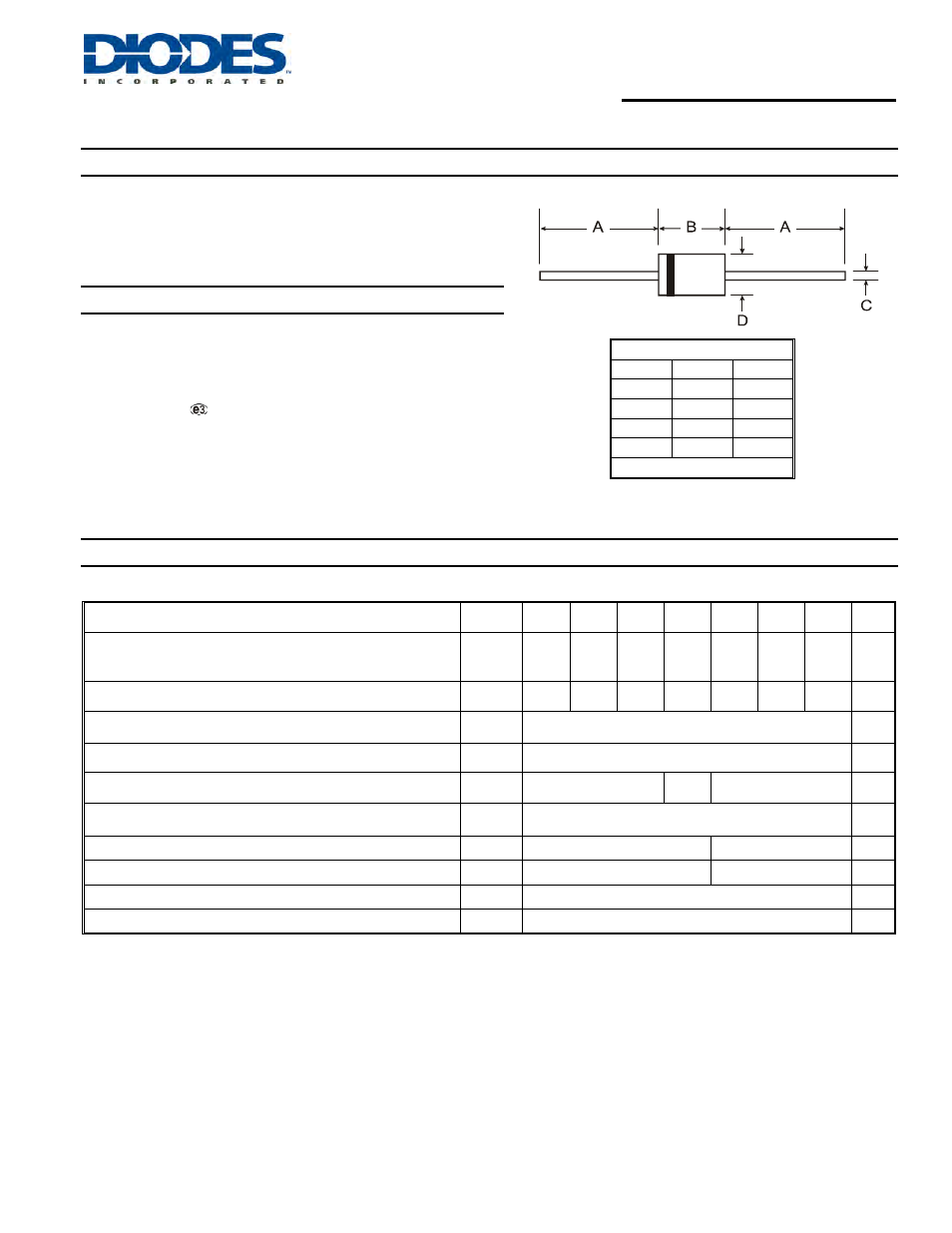
Case: DO-15
•
Case Material: Molded Plastic. UL Flammability Classification
Rating 94V-0
•
Moisture Sensitivity: Level 1 per J-STD-020D
•
Terminals: Finish – Tin. Solderable per MIL-STD-202,
Method 208
•
Polarity: Cathode Band
•
Marking: Type Number
•
Ordering Information: See Page 3
•
Weight: 0.4 grams (approximate)
DO-15
Dim
Min
Max
A
25.40
⎯
B
5.50
7.62
C
0.686
0.889
D
2.60
3.60
All Dimensions in mm
Maximum Ratings and Electrical Characteristics
@T
A
= 25°C unless otherwise specified
Single phase, half wave, 60Hz, resistive or inductive load.
For capacitive load, derate current by 20%.
DS25007 Rev. 4 - 2
1 of 3
www.diodes.com
UF2001 - UF2007
© Diodes Incorporated
Characteristic
Symbol
UF
2001
UF
2002
UF
2003
UF
2004
UF
2005
UF
2006
UF
2007
Unit
Peak Repetitive Reverse Voltage
Working Peak Reverse Voltage
DC Blocking Voltage (Note 5)
V
RRM
V
RWM
V
R
50
100
200
400
600
800
1000
V
RMS Reverse Voltage
V
R(RMS)
35
70
140
280
420
560
700
V
Average Rectified Output Current
(Note 1) @ T
A
= 50
°C
I
O
2.0
A
Non-Repetitive Peak Forward Surge Current
8.3ms Single Half Sine-Wave Superimposed on Rated Load
I
FSM
60
A
Forward Voltage @ I
F
= 2.0A
V
FM
1.0
1.3
1.7
V
Peak Reverse Current @ T
A
= 25
°C
at Rated DC Blocking Voltage (Note 5) @ T
A
= 100
°C
I
RM
5.0
100
μA
Reverse Recovery Time (Note 3)
t
rr
50
75
ns
Typical Total Capacitance (Note 2)
C
T
50
30
pF
Typical Thermal Resistance Junction to Ambient
R
θJA
50
°C/W
Operating and Storage Temperature Range
T
J,
T
STG
-65 to +150
°C
Notes:
1. Valid provided that leads are maintained at ambient temperature at a distance of 9.5mm from the case.
2. Measured at 1.0MHz and applied reverse voltage of 4.0V DC.
3. Measured at I
F
= 0.5A, I
R
= 1.0A, I
rr
= 0.25A. See figure 5.
4. RoHS revision 13.2.2003. High temperature solder exemption applied, see EU Directive Annex Note 7.
5. Short duration pulse test used to minimize self heating effect.