Diodes SF10AG - SF10JG User Manual
Sf10ag - sf10jg, 0a super-fast glass passivated rectifier features, Maximum ratings and electrical characteristics
e
3
DS24012 Rev. 4 - 2
1 of 3
SF10AG - SF10JG
www.diodes.com
ã
Diodes Incorporated
SF10AG - SF10JG
1.0A SUPER-FAST GLASS PASSIVATED RECTIFIER
Features
A
A
B
C
D
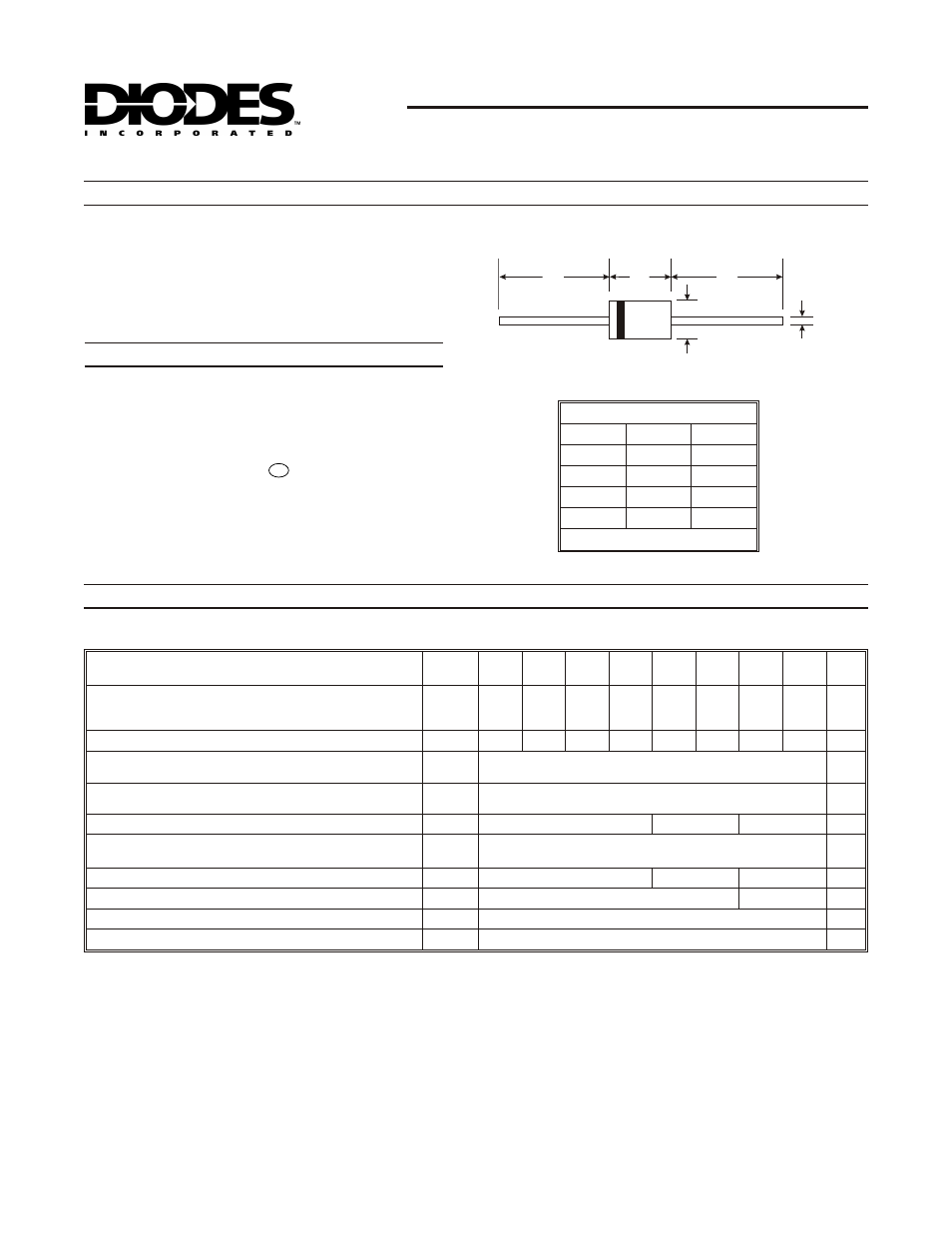
DO-41
Dim
Min
Max
A
25.40
¾
B
4.06
5.21
C
0.71
0.864
D
2.00
2.72
All Dimensions in mm
Maximum Ratings and Electrical Characteristics
@ T
A
= 25°C unless otherwise specified
·
Glass Passivated Die Construction
·
Super-Fast Switching for High Efficiency
·
Surge Overload Rating to 30A Peak
·
Low Reverse Leakage Current
·
Lead Free Finish, RoHS Compliant (Note 4)
Mechanical Data
·
Case: DO-41
·
Case Material: Molded Plastic. UL Flammability
Classification Rating 94V-0
·
Moisture Sensitivity: Level 1 per J-STD-020C
·
Terminals: Finish - Tin. Plated Leads Solderable per
MIL-STD-202, Method 208
·
Polarity: Cathode Band
·
Marking: Type Number
·
Ordering Information: See Last Page
·
Weight: 0.3 grams (approximate)
Single phase, half wave, 60Hz, resistive or inductive load.
For capacitive load, derate current by 20%.
Characteristic
Symbol
SF10
AG
SF10
BG
SF10
CG
SF10
DG
SF10
FG
SF10
GG
SF10
HG
SF10
JG
Unit
Peak Repetitive Reverse Voltage
Working Peak Reverse Voltage
DC Blocking Voltage (Note 5)
V
RRM
V
RWM
V
R
50
100
150
200
300
400
500
600
V
RMS Reverse Voltage
V
R(RMS)
35
70
105
140
210
280
350
420
V
Average Rectified Output Current
@ T
A
= 75°C
(Note 1)
I
O
1.0
A
Non-Repetitive Peak Forward Surge Current
8.3ms Single half sine-wave Superimposed on Rated Load
I
FSM
30
A
Forward Voltage
@ I
F
= 1.0A
V
FM
0.95
1.3
1.5
V
Peak Reverse Current
@ T
A
= 25°C
at Rated DC Blocking Voltage (Note 5)
@ T
A
= 100°C
I
RM
10
100
m
A
Reverse Recovery Time (Note 3)
t
rr
35
40
50
ns
Typical Total Capacitance (Note 2)
C
T
75
50
pF
Thermal Resistance Junction to Ambient
R
q
JA
75
°C/W
Operating and Storage Temperature Range
T
j
,
T
STG
-65 to +150
°
C
Notes: 1. Valid provided that leads are maintained at ambient temperature at a distance of 9.5mm from the case.
2. Measured at 1.0MHz and applied reverse voltage of 4.0V DC.
3. Measured with I
F
= 0.5A, I
R
= 1.0A, Irr = 0.25A. (See Figure 5)
4. RoHS 5. Short duration pulse test used to minimize self-heating effect