Diodes PR1001G - PR1007G User Manual
Features, Mechanical data, Maximum ratings and electrical characteristics
DS27001 Rev. 9 - 2
1 of 3
www.diodes.com
PR1001G - PR1007G
© Diodes Incorporated
PR1001G - PR1007G
1.0A FAST RECOVERY GLASS PASSIVATED RECTIFIER
Features
•
Glass Passivated Die Construction
•
Fast Switching for High Efficiency
•
Surge Overload Rating to 30A Peak
•
Low Reverse Leakage Current
•
Lead Free Finish, RoHS Compliant (Note 4)
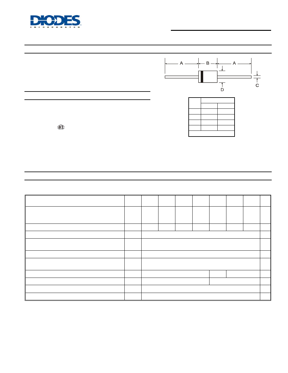
Mechanical Data
•
Case: DO-41 Plastic
•
Case Material: Molded Plastic. UL Flammability Classification
Rating 94V-0
•
Moisture Sensitivity: Level 1 per J-STD-020D
•
Terminals: Finish - Tin. Plated Leads Solderable per MIL-STD-202,
Method 208
•
Polarity: Cathode Band
•
Marking: Type Number
•
Ordering Information: See Page 3
•
Weight: 0.35 grams (approximate)
Dim
DO-41 Plastic
Min
Max
A
25.40
⎯
B
4.06
5.21
C
0.71
0.864
D
2.00
2.72
All Dimensions in mm
Maximum Ratings and Electrical Characteristics
@T
A
= 25°C unless otherwise specified
Single phase, half wave, 60Hz, resistive or inductive load.
For capacitive load, derate current by 20%.
Characteristic
Symbol
PR1001
G
PR1002
G
PR1003
G
PR1004
G
PR1005
G
PR1006
G
PR1007
G
Unit
Peak Repetitive Reverse Voltage
Working Peak Reverse Voltage
DC Blocking Voltage (Note 5)
V
RRM
V
RWM
V
R
50
100
200
400
600
800
1000
V
RMS Reverse Voltage
V
R(RMS)
35
70
140
280
420
560
700
V
Average Rectified Output Current (Note 1) @ T
A
= 55
°C
I
O
1.0
A
Non-Repetitive Peak Forward Surge Current 8.3ms
Single Half Sine-Wave Superimposed on Rated Load
I
FSM
30
A
Forward Voltage Drop @ I
F
= 1.0A
V
FM
1.3
V
Peak Reverse Current @ T
A
= 25
°C
at Rated DC Blocking Voltage (Note 5) @ T
A
= 100
°C
I
RM
5.0
50
μA
Reverse Recovery Time (Note 3)
t
rr
150
250
500
ns
Typical Total Capacitance (Note 2)
C
T
15
8
pF
Typical Thermal Resistance Junction to Ambient
R
θJA
95
°C/W
Operating and Storage Temperature Range
T
J,
T
STG
-65 to +150
°C
Notes:
1. Valid provided that leads are maintained at ambient temperature at a distance of 9.5mm from the case.
2. Measured at 1.0MHz and applied reverse voltage of 4.0V DC.
3. Measured with I
F
= 0.5A, I
R
= 1.0A, I
rr
= 0.25A. See figure 5.
4. EU Directive 2002/95/EC (RoHS). All applicable RoHS exemptions applied, see5. Short duration pulse test used to minimize self-heating effect.