Sbr20a60ctq, Maximum ratings (per leg), Thermal characteristics (per leg) – Diodes SBR20A60CTQ User Manual
Page 2: Electrical characteristics, Per leg)
SBR is a registered trademark of Diodes Incorporated.
SBR20A60CTBQ
Document number: DS36363 Rev. 1 - 2
2 of 5
July 2013
© Diodes Incorporated
SBR20A60CTQ
Maximum Ratings (Per Leg)
(@T
A
= +25°C, unless otherwise specified.)
Single phase, half wave, 60Hz, resistive or inductive load.
For capacitance load, derate current by 20%.
Characteristic Symbol
Value
Unit
Peak Repetitive Reverse Voltage
Working Peak Reverse Voltage
DC Blocking Voltage
V
RRM
V
RWM
V
RM
60 V
Average Rectified Output Current Per Device
I
O
20 A
Non-Repetitive Peak Forward Surge Current 8.3ms
Single Half Sine-Wave Superimposed on Rated Load
I
FSM
180 A
Peak Repetitive Reverse Surge Current (2
μS - 1Khz)
I
RRM
3 A
Repetitive Peak Avalanche Power (1
μs, +25°C)
P
ARM
7000 W
Non-Repetitive Avalanche Energy (T
J
= +25°C, I
AS
= 12A L = 10mH)
E
AS
500 mJ
Thermal Characteristics (Per Leg)
Characteristic Symbol
Value
Unit
Typical Thermal Resistance
Thermal Resistance Junction to Case (Note 5)
Thermal Resistance Junction to Ambient (Note 5)
R
θJC
R
θJA
4
8
°C/W
Operating and Storage Temperature Range
T
J
, T
STG
-65 to +150
°C
Electrical Characteristics
(Per Leg)
(@T
A
= +25°C, unless otherwise specified.)
Characteristic Symbol
Min
Typ
Max
Unit
Test
Condition
Forward Voltage Drop
V
F
—
—
—
0.50
0.47
0.63
—
—
0.79
V
I
F
= 10A, T
J
= +25°C
I
F
= 10A, T
J
= +125°C
I
F
= 20A, T
J
= +25°C
Leakage Current (Note 6)
I
R
—
—
0.14
45
0.5
—
mA
V
R
= 60V, T
J
= +25°C
V
R
= 60V, T
J
= +125°C
Notes:
5. Mounted heatsink black Aluminum, 45mm*20mm*12mm, minimum recommended pad layout as shown on Diodes Inc. suggested pad layout document
AP02001, which can be found on our website
6. Short duration pulse test used to minimize self-heating effect.
I
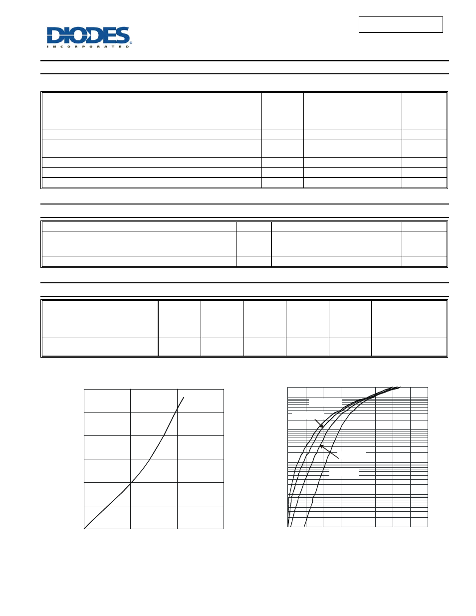
AVERAGE FORWARD CURRENT (A)
Figure 1 Forward Power Dissipation
F(AV)
P
, A
V
E
R
A
G
E
F
O
R
WA
R
D
P
O
W
E
R DISSI
P
A
T
ION
(W
)
F(
A
V
)
0
1
2
3
4
5
6
0
5
10
15
0.001
0.01
0.1
1
10
0
100
200
300
400
500
600
700 800
Figure 2 Typical Forward Characteristics
V , INSTANTANEOUS FORWARD VOLTAGE (mV)
F
I
, IN
ST
ANT
A
NE
O
U
S
F
O
RW
AR
D CURR
EN
T
(
A
)
F
T = +25°C
A
T = +85°C
A
T = +125°C
A
T = +150°C
A
20
Note: 7. Mounted heatsink, black Aluminum, 45mm*20mm*12mm,min recommended pad layout layout.