Maximum ratings, Thermal characteristics, Electrical characteristics – Diodes SBR12U100P5Q User Manual
Page 2
SBR12U100P5Q
Document number: DS36325 Rev. 1 - 0
2 of 5
July 2013
© Diodes Incorporated
SBR12U100P5Q
SBR and POWERDI are registered trademarks of Diodes Incorporated.
Maximum Ratings
(@T
A
= +25°C, unless otherwise specified.)
Single phase, half wave, 60Hz, resistive or inductive load.
For capacitance load, derate current by 20%.
Characteristic Symbol
Value
Unit
Peak Repetitive Reverse Voltage
Working Peak Reverse Voltage
DC Blocking Voltage
V
RRM
V
RWM
V
RM
100 V
Average Rectified Output Current
I
O
12 A
Non-Repetitive Peak Forward Surge Current 8.3ms
Single Half Sine-Wave Superimposed on Rated Load
I
FSM
250 A
Non-Repetitive Avalanche Energy
(T
J
= +25°C, I
AS
= 12A, L = 10mH)
E
AS
592 mJ
Repetitive Peak Avalanche Energy (1µs, +25°C)
P
ARM
12000 W
Thermal Characteristics
Characteristic Symbol
Value
Unit
Typical Thermal Resistance Junction to Ambient (Note 6)
R
θJA
27 °C/W
Typical Thermal Resistance Junction to Lead
R
θJL
3
°C/W
Operating and Storage Temperature Range
T
J,
STG
-55 to +150
°C
Electrical Characteristics
(@T
A
= +25°C, unless otherwise specified.)
Characteristic Symbol
Min
Typ
Max
Unit
Test
Condition
Forward Voltage Drop
V
F
—
—
—
0.49
0.67
0.58
—
0.78
—
V
I
F
= 5A, T
J
= +25°C
I
F
= 12A, T
J
= +25°C
I
F
= 12A, T
J
= +125°C
Leakage Current (Note 7)
I
R
—
—
0.06
11
0.25
40
mA
V
R
= 100V, T
J
= +25°C
V
R
= 100V, T
J
= +125°C
Notes:
6. Polymide, 2oz. Copper 16x minimum recommended pad layout per7. Short duration pulse test used to minimize self-heating effect.
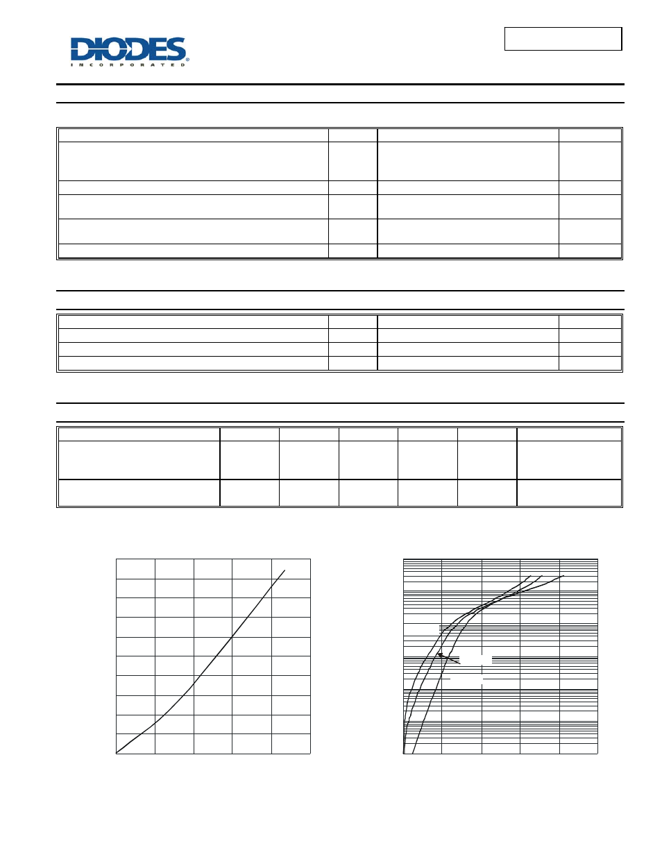
P
, POW
E
R DI
SSIP
A
T
ION
(W
)
D
0
0.5
1.0
1.5
2.0
2.5
3.0
3.5
4.0
4.5
5.0
0
2
4
6
8
10
I
AVERAGE FORWARD CURRENT (A)
Figure 1 Forward Power Dissipation
F(AV)
Note 6
0.0001
0.001
0.01
0.1
1
10
100
V , INSTANTANEOUS FORWARD VOLTAGE (V)
F
Figure 2 Typical Forward Characteristics
0
0.2
0.4
0.6
0.8
1.0
I
, INS
T
AN
T
ANE
O
U
S F
O
R
WA
R
D
C
U
R
R
EN
T
(A
)
F
T = 25°C
A
T = 85°C
A
T = 125°C
A