Maximum ratings, Thermal characteristics, Electrical characteristics – Diodes SBRT20M60SP5 User Manual
Page 2
POWERDI are registered trademarks of Diodes Incorporated.
SBRT20M60SP5
Document number: DS36826 Rev. 3 - 2
2 of 4
March 2014
© Diodes Incorporated
SBRT20M60SP5
NEW PROD
UC
T
ADVANCED INFORMATION
Maximum Ratings
(@T
A
= +25°C, unless otherwise specified.)
Characteristic Symbol
Value
Unit
Peak Repetitive Reverse Voltage
Working Peak Reverse Voltage
DC Blocking Voltage
V
RRM
60 V
Average Rectified Output Current
Io
20
A
Non-Repetitive Peak Forward Surge Current 8.3mS
I
FSM
320 A
Thermal Characteristics
Characteristic Symbol
Value
Unit
Typical Thermal Resistance Junction to Ambient (Note 6)
R
θJA
10 °C/W
Typical Thermal Resistance Junction to Case (Note 6)
R
θJC
2 °C/W
Operating and Storage Temperature Range
T
J,
T
STG
-55 to +150
°C
Electrical Characteristics
(@T
A
= +25°C, unless otherwise specified.)
Notes:
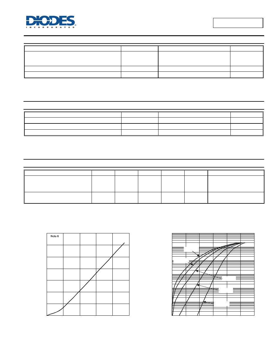
6. Device mounted on 2 oz. PCB with heatsink 50mm*50mm*23mm.
7. Short duration pulse test used to minimize self-heating effect.
P
, P
O
WE
R
D
ISS
IP
A
T
IO
N
(W
)
D
0
2
4
6
8
10
12
14
0
5
10
15
20
25
T = 150
J
I
AVERAGE RECTIFIED OUTPUT CURRENT (A)
Figure 1 Forward Power Dissipation
F(AV)
V , INSTANTANEOUS FORWARD VOLTAGE (mV)
F
Figure 2 Typical Forward Characteristics
I,
I
N
S
TAN
TANE
O
U
S F
O
R
WA
R
D
C
U
R
R
EN
T
(A
)
F
0.0001
0.001
0.01
0.1
1
10
100
0
100
200
300
400
500
600
T = 25°C
A
T = 85°C
A
T = 125°C
A
T = 150°C
A
T = -55°C
A
Characteristic Symbol
Min
Typ
Max
Unit
Test
Condition
Forward Voltage Drop
V
F
—
—
—
0.43
0.52
0.38
—
0.57
0.43
V
I
F
= 10A, T
A
= +25°C
I
F
= 20A, T
A
= +25°C
I
F
= 10A, T
A
= +125°C
Leakage Current (Note 7)
I
R
—
—
0.04
—
0.18
45
mA
V
R
= 60V , T
A
= +25°C
V
R
= 60V , T
A
= +125°C