Sbr8u20sp5, New prod uc t, Maximum ratings – Diodes SBR8U20SP5 User Manual
Page 2: Thermal characteristics, Electrical characteristics
SBR8U20SP5
Document number: DS35668 Rev. 2 - 2
2 of 4
January 2012
© Diodes Incorporated
SBR8U20SP5
SBR and POWERDI are registered trademarks of Diodes Incorporated.
NEW PROD
UC
T
Maximum Ratings
@T
A
= 25°C unless otherwise specified
Single phase, half wave, 60Hz, resistive or inductive load.
For capacitance load, derate current by 20%.
Characteristic Symbol
Value
Unit
Peak Repetitive Reverse Voltage
Working Peak Reverse Voltage
DC Blocking Voltage
V
RRM
V
RWM
V
RM
20 V
Average Rectified Output Current
I
O
8 A
Non-Repetitive Peak Forward Surge Current 8.3ms
Single Half Sine-Wave Superimposed on Rated Load
I
FSM
180 A
Thermal Characteristics
Characteristic Symbol
Value
Unit
Maximum Thermal Resistance
Thermal Resistance Junction to Ambient (Note 3)
Thermal Resistance Junction to Ambient (Note 4)
R
θJA
R
θJA
102
60
ºC/W
Operating Temperature Range
V
R
≤ 80% V
RRM
T
J
-65 to +150
ºC
V
R
≤ 50% V
RRM
≤180
DC Forward Mode
≤200
Storage Temperature Range
T
STG
-65 to +175
ºC
Electrical Characteristics
@T
A
= 25°C unless otherwise specified
Characteristic Symbol
Min
Typ
Max
Unit
Test
Condition
Forward Voltage Drop
V
F
-
-
0.41
0.33
0.51
0.43
V
I
F
= 8A, T
J
= 25ºC
I
F
= 8A, T
J
= 125ºC
Leakage Current (Note 5)
I
R
-
-
0.08
0.2
0.2
0.5
mA
V
R
= 4V, T
J
= 25ºC
V
R
= 20V, T
J
= 25ºC
Notes:
3. FR-4 PCB, 2oz. Copper, minimum recommended pad lay
4. Polymide PCB, 2oz. Copper. Cathode pad dimensions 18.8mm x 14.4mm. Anode pad dimensions 5.6mm x 14.4mm.
5. Short duration pulse test used to minimize self-heating effect.
0
0.5
1.0
1.5
2.0
2.5
3.0
3.5
4.0
4.5
5.0
0
2
4
6
8
10
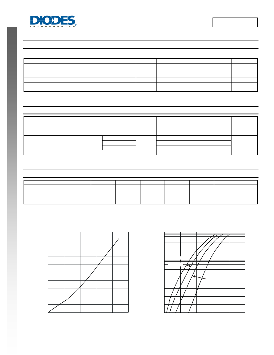
Fig. 1 Forward Power Dissipation
I
, AVERAGE FORWARD CURRENT (A)
F(AV)
P
,
P
O
WE
R
DI
SSI
P
A
T
IO
N (
W
)
D
T = 175°C
A
0.01
0
100
200
300
400
500
0.1
1
10
Fig. 2 Typical Forward Characteristics
V , INSTANTANEOUS FORWARD VOLTAGE (mV)
F
I
, I
N
ST
ANT
A
NE
O
U
S F
O
RW
ARD
C
URRENT
(
A
)
F
T = 25°C
A
T = 85°C
A
T = 125°C
A
T = 150°C
A