Maximum ratings (per leg), Thermal characteristics, Per leg) – Diodes SBR40U300CTB User Manual
Page 2: Electrical characteristics
SBR40U300CTB
Document number: DS31400 Rev. 5 - 2
2 of 4
July 2011
© Diodes Incorporated
SBR40U300CTB
SBR is a registered trademark of Diodes Incorporated.
Maximum Ratings (Per Leg)
@T
A
= 25°C unless otherwise specified
Single phase, half wave, 60Hz, resistive or inductive load.
For capacitance load, derate current by 20%.
Characteristic Symbol
Value
Unit
Peak Repetitive Reverse Voltage
Working Peak Reverse Voltage
DC Blocking Voltage
V
RRM
V
RWM
V
RM
300 V
Average Rectified Output Current
Per Leg
Total
I
O
20
40
A
Non-Repetitive Peak Forward Surge Current 8.3ms
Single Half Sine-Wave Superimposed on Rated Load
I
FSM
200 A
Thermal Characteristics
(Per Leg)
Characteristic Symbol
Value
Unit
Typical Thermal Resistance
Thermal Resistance Junction to Case (Note 4)
R
θJC
2
°C/W
Operating and Storage Temperature Range
T
J
, T
STG
-65 to +175
ºC
Electrical Characteristics
(Per Leg)
@T
A
= 25°C unless otherwise specified
Characteristic Symbol
Min
Typ
Max
Unit
Test
Condition
Forward Voltage Drop (per leg)
V
F
-
0.87
-
0.92
0.81
V
I
F
= 20A, T
J
= 25ºC
I
F
= 20A, T
J
= 125ºC
Leakage Current (Note 5)
I
R
-
-
-
100
50
μA
mA
V
R
= 300V, T
J
= 25ºC
V
R
= 300V, T
J
= 125ºC
Reverse Recovery Time
t
rr
- 32 50
ns
I
F
= 0.5A, I
R
= 1A, I
RR
= 0.25A
- 26 35
I
F
= 1A, V
R
= 30V,
di/dt = 100A/
μs, T
J
= 25ºC
Notes:
4. FR-4 PCB, 2 oz. Copper, minimum recommended pad lay5. Short duration pulse test used to minimize self-heating effect.
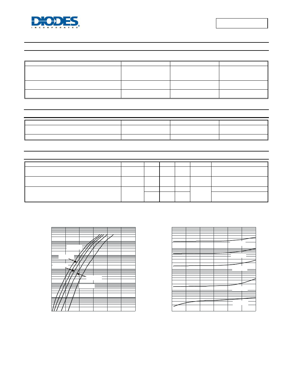
Fig.1 Typical Forward Characteristics
0
0.2
0.4
0.6
0.8
1
1.2
V , INSTANTANEOUS FORWARD VOLTAGE (V)
F
0.0001
0.01
0.1
1
10
100
I,
I
N
S
T
AN
T
AN
E
O
U
S
F
O
R
WA
R
D
C
U
R
R
EN
T
(A
)
F
0.001
T = 25 C
A
°
T = 85 C
A
°
T = 125 C
A
°
T = 150 C
A
°
T = 175 C
A
°
0.1
1
10
100
1,000
I,
I
N
S
T
AN
T
AN
E
O
U
S
R
EV
E
R
SE
C
U
R
R
EN
T
(A
)
R
µ
Fig. 2 Typical Reverse Characteristics
0
50
100
150
200
250
300
V , INSTANTANEOUS REVERSE VOLTAGE (V)
R
T = 25 C
A
°
T = 85 C
A
°
T = 125 C
A
°
T = 175 C
A
°
T = 150 C
A
°