Maximum ratings (per leg), Thermal characteristics (per leg), Electrical characteristics (per leg) – Diodes SBR30A45CTFP User Manual
Page 2
SBR is a registered trademark of Diodes Incorporated.
SBR30A45
Document number: DS30981 Rev. 8 - 2
2 of 5
August 2012
© Diodes Incorporated
SBR30A45CT
SBR30A45CTFP
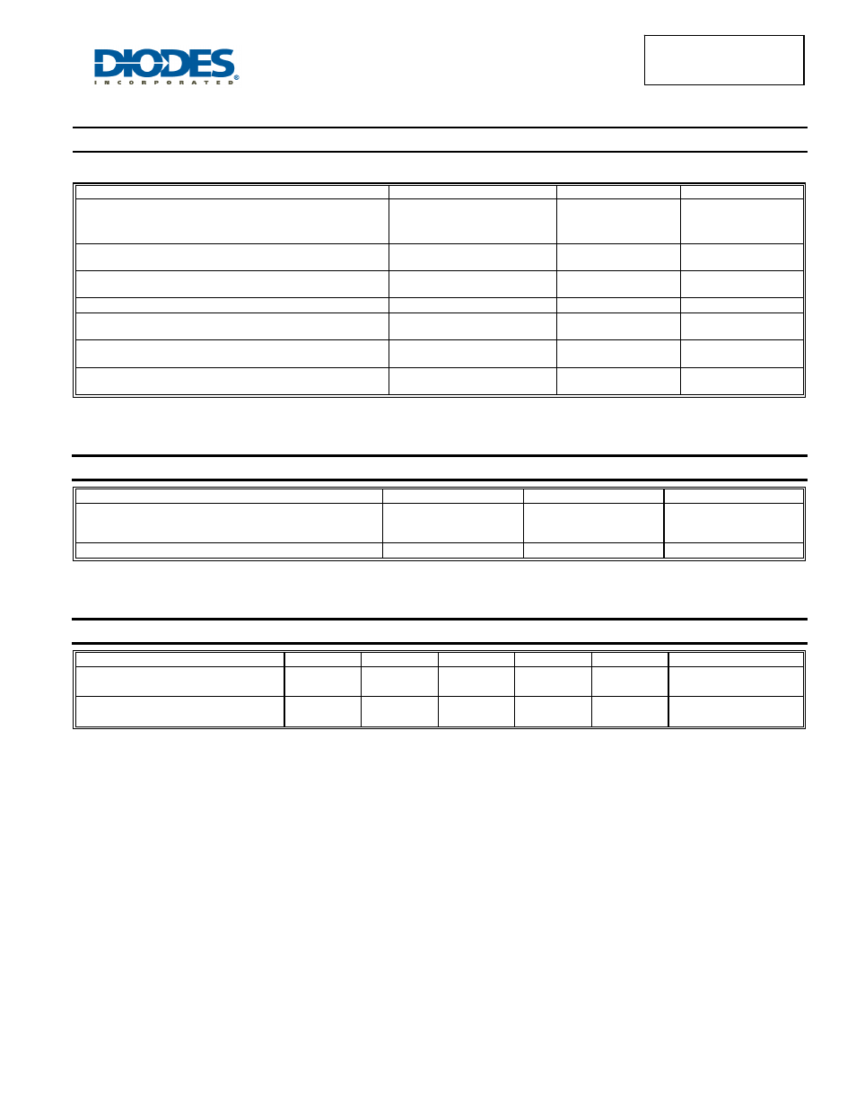
Maximum Ratings (Per Leg)
(@T
A
= +25°C, unless otherwise specified.)
Single phase, half wave, 60Hz, resistive or inductive load.
For capacitance load, derate current by 20%.
Characteristic Symbol
Value
Unit
Peak Repetitive Reverse Voltage
Working Peak Reverse Voltage
DC Blocking Voltage
V
RRM
V
RWM
V
RM
45 V
Average Rectified Output Current Per Device
(Per Leg)
(Total)
I
O
15
30
A
Non-Repetitive Peak Forward Surge Current 8.3ms
Single Half Sine-Wave Superimposed on Rated Load
I
FSM
250 A
Peak Repetitive Reverse Surge Current (2
μS - 1Khz)
I
RRM
3 A
Repetitive Peak Avalanche Power
(1
μs, +25ºC)
P
ARM
8000
W
Non-Repetitive Avalanche Energy
(T
J
= +25°C, I
AS
= 5A, L = 8.5mH)
E
AS
600
mJ
Isolation Voltage (ITO-220AB Only)
From terminal to heatsink t = 3 sec.
V
AC
2000 V
Thermal Characteristics (Per Leg)
Characteristic Symbol
Value
Unit
Typical Thermal Resistance
Package = TO-220AB
Package = ITO-220AB
R
θJC
2
4
ºC/W
Operating and Storage Temperature Range
T
J
, T
STG
-65 to +150
ºC
Electrical Characteristics (Per Leg)
(@T
A
= +25°C, unless otherwise specified.)
Characteristic Symbol
Min
Typ
Max
Unit
Test
Condition
Forward Voltage Drop
V
F
-
-
0.42
0.50
0.45
V
I
F
= 15A, T
J
= +25ºC
I
F
= 15A, T
J
= +125ºC
Leakage Current (Note 6)
I
R
- -
0.5
100
mA
V
R
= 45V, T
J
= +25ºC
V
R
= 45V, T
J
= +125ºC
Notes:
6. Short duration pulse test used to minimize self-heating effect.