Maximum ratings, Thermal characteristics, Electrical characteristics – Diodes SBR20A40CTFP User Manual
Page 2: Sbr20a40
SBR is a registered trademark of Diodes Incorporated.
SBR20A40
Document number: DS30963 Rev. 6 - 2
2 of 4
April 2012
© Diodes Incorporated
SBR20A40CT
SBR20A40CTFP
Maximum Ratings
@T
A
= 25°C unless otherwise specified
Single phase, half wave, 60Hz, resistive or inductive load.
For capacitance load, derate current by 20%.
Characteristic Symbol
Value
Unit
Peak Repetitive Reverse Voltage
Working Peak Reverse Voltage
DC Blocking Voltage
V
RRM
V
RWM
V
RM
40 V
Average Rectified Output Current @ T
C
= 110ºC
I
O
20 A
Non-Repetitive Peak Forward Surge Current 8.3ms
Single Half Sine-Wave Superimposed on Rated Load
I
FSM
180 A
Peak Repetitive Reverse Surge Current (2uS-1Khz)
I
RRM
3 A
Isolation Voltage (ITO-220AB Only)
From terminal to heatsink t = 3 sec.
V
AC
2000 V
Thermal Characteristics
Characteristic Symbol
Value
Unit
Typical Thermal Resistance (per leg)
Package = TO-220AB
Package = ITO-220AB
R
θJC
2
4
°C/W
Operating and Storage Temperature Range
T
J
, T
STG
-65 to +150
ºC
Electrical Characteristics
@T
A
= 25°C unless otherwise specified
Characteristic Symbol
Min
Typ
Max
Unit
Test
Condition
Forward Voltage Drop
V
F
-
-
0.41
-
0.50
0.47
0.60
V
I
F
= 10A, T
J
= 25ºC
I
F
= 10A, T
J
= 125ºC
I
F
= 20A, T
J
= 25ºC
Leakage Current (Note 6)
I
R
- -
0.5
100
mA
V
R
= 40V, T
J
= 25ºC
V
R
= 40V, T
J
= 125ºC
Notes:
6. Short duration pulse test used to minimize self-heating effect.
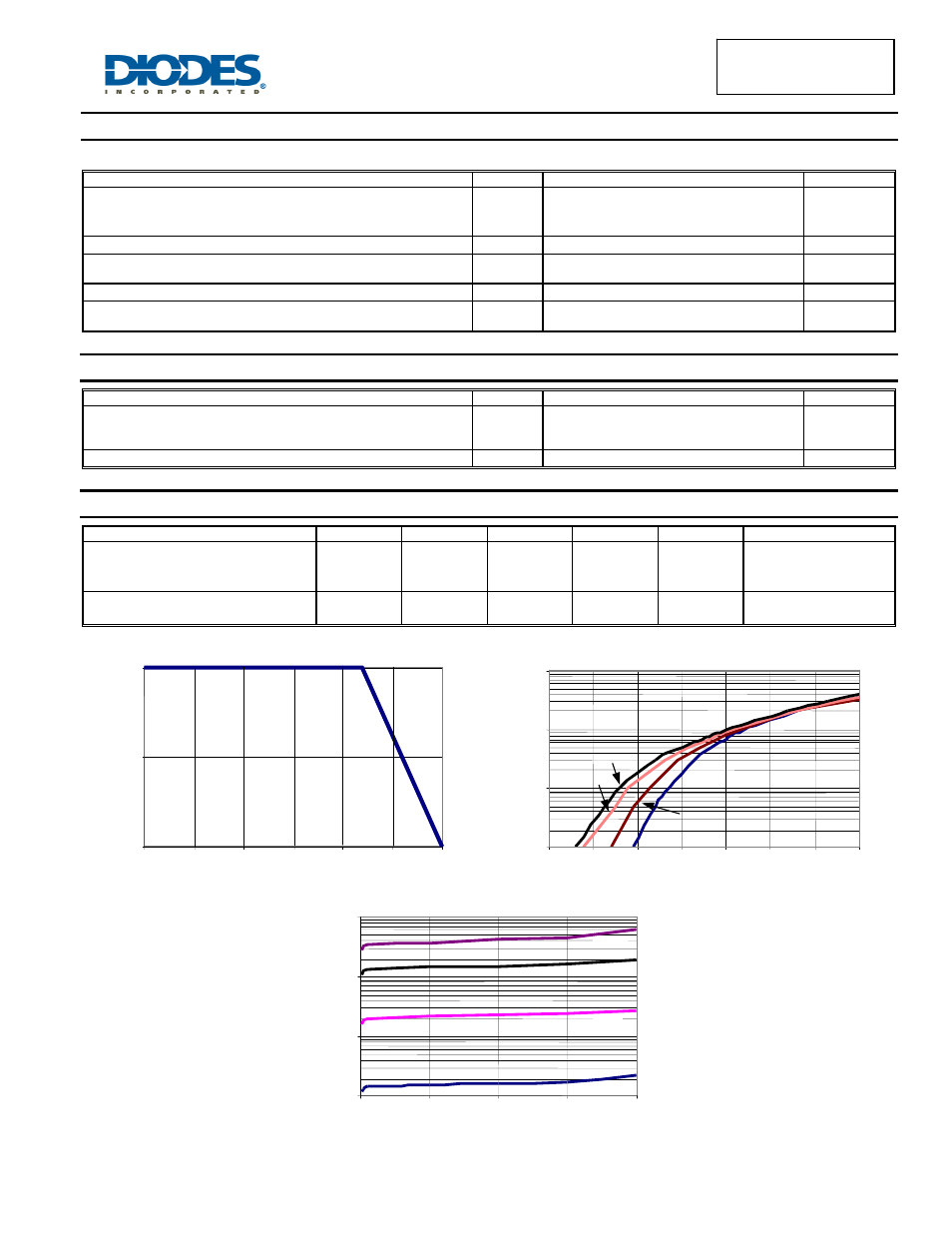
0
5
10
0
25
50
75
100
125
150
T
C
CASE TEMPERATURE (
°C)
I
F(A
VE)
, AVERAGE F
O
RWARD CURRENT
(
A)
0.1
1
10
100
0.00
0.10
0.20
0.30
0.40
0.50
0.60
0.70
V
F
, INSTANTANEOUS FORWARD VOLTAGE (V)
I
F
, I
NS
T
ANT
ANE
O
US
F
O
RW
ARD CURRE
NT
(
A)
Tj=25
°C
Tj=125
°C
Tj=150
°C
Tj=75
°C
Figure 1: Current Derating Curve, Per Element
Figure 2: Typical Forward Characteristics, Per Element
0.1
1
10
100
0
10
20
30
40
V
R
, INSTANTANEOUS REVERSE VOLTAGE (V)
I
R
, I
N
ST
A
N
T
A
N
EO
U
S R
EVER
SE C
U
R
R
EN
T
(m
A
)
Tj=150
°C
Tj=25
°C
Tj=125
°C
Tj=75
°C
Figure 3: Typical Reverse Characteristics, Per Element