Maximum ratings, Thermal characteristics, Electrical characteristics – Diodes SBR15U50SP5 User Manual
Page 2
SBR and POWERDI are registered trademarks of Diodes Incorporated.
SBR15U50SP5
Document number: DS36167 Rev. 4 - 2
2 of 5
May 2013
© Diodes Incorporated
SBR15U50SP5
NEW PROD
UC
T
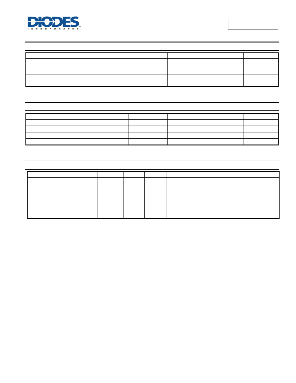
Maximum Ratings
(@T
A
= +25°C, unless otherwise specified.)
Characteristic Symbol
Value
Unit
Peak Repetitive Reverse Voltage
Working Peak Reverse Voltage
DC blocking Voltage
V
RRM
50 V
Average Rectified Output Current
Io
15
A
Non-Repetitive Peak Forward Surge Current 8.3mS
I
FSM
256 A
Thermal Characteristics
Characteristic Symbol
Value
Unit
Typical Thermal Resistance (Note 5)
R
θJA
97 °C/W
Typical Thermal Resistance (Note 6)
R
θJA
39 °C/W
Typical Thermal Resistance (Note 7)
R
θJM
4 °C/W
Operating and Storage Temperature Range
T
J,
T
STG
-65 to +150
°C
Electrical Characteristics
(@T
A
= +25°C, unless otherwise specified.)
Characteristic Symbol
Min
Typ
Max
Unit
Test
Condition
Forward Voltage Drop
V
F
—
—
—
—
—
0.33
0.44
0.40
0.48
—
0.52
—
V
I
F
=10A, T
J
= +25°C
I
F
=10A, T
J
= +125°C
I
F
=15A, T
J
= +25°C
I
F
=15A, T
J
= +125°C
Leakage Current (Note 8)
I
R
—
—
—
50
0.5
—
mA
V
R
= 50V , T
J
= +25°C
V
R
= 50V , T
J
= +125°C
Junction Capacitance
C
J
—
400 — pF
V
R
= 25V , T
J
= +25°C
Notes:
5. FR-4 PCB, 2oz. Copper, minimum recommended pad lay
6. FR-4 PCB, 2oz. Copper. Cathode pad dimensions 18.8mm x 14.4mm. Anode pad dimensions 5.6mm x 14.4mm.
7. Junction to Mount (Cathode Terminal)
8. Short duration pulse test used to minimize self-heating effect.