Maximum ratings, Thermal characteristics, Electrical characteristics – Diodes SBR10U45D1 User Manual
Page 2
SBR10U45D1
Document number: DS31069 Rev. 7 - 2
2 of 5
April 2011
© Diodes Incorporated
SBR10U45D1
SBR is a registered trademark of Diodes Incorporated.
Maximum Ratings
@T
A
= 25°C unless otherwise specified
Single phase, half wave, 60Hz, resistive or inductive load.
For capacitance load, derate current by 20%.
Characteristic Symbol
Value
Unit
Peak Repetitive Reverse Voltage
Working Peak Reverse Voltage
DC Blocking Voltage
V
RRM
V
RWM
V
RM
45 V
RMS Reverse Voltage
V
R(RMS)
31 V
Average Rectified Output Current @T
C
= 110ºC
I
O
10 A
Non-Repetitive Peak Forward Surge Current 8.3ms
Single Half Sine-Wave Superimposed on Rated Load
I
FSM
125 A
Thermal Characteristics
@T
A
= 25°C unless otherwise specified
Characteristic Symbol
Value
Unit
Typical Thermal Resistance
Thermal Resistance Junction to Case
Thermal Resistance Junction to Ambient (Note 3)
R
θJC
R
θJA
2.0
34
°C/W
Operating and Storage Temperature Range
T
J
, T
STG
-65 to +150
ºC
Electrical Characteristics
@T
A
= 25°C unless otherwise specified
Characteristic Symbol
Min
Typ
Max
Unit
Test
Condition
Forward Voltage Drop
V
F
-
-
-
0.57
0.54
V
I
F
= 10A, T
J
= 25ºC
I
F
= 10A, T
J
= 125ºC
Leakage Current (Note 4)
I
R
- -
0.5
mA
V
R
= 45V, T
J
= 25ºC
Notes:
3. Polymide PCB 2 oz. Copper, minimum recommended pad layout as shown on Diodes Inc. suggested pad layout document AP02001, which can be
found on our website at
4. Short duration pulse test used to minimize self-heating effect.
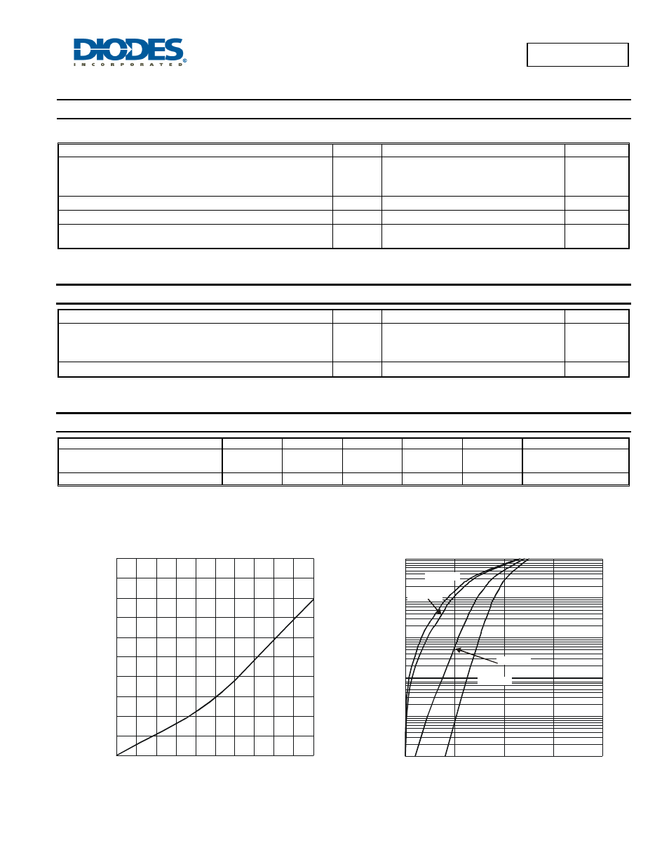
0
0.5
1.0
1.5
2.0
2.5
3.0
3.5
4.0
4.5
5.0
0
1
2
3
4
5
6
7
8
9
10
Fig. 1 Forward Power Dissipation
I
, AVERAGE FORWARD CURRENT (A)
F(AV)
P
,
P
O
WE
R
D
ISSI
P
A
T
IO
N (
W
)
D
0.0001
0.001
0.01
0.1
1
10
0
200
400
600
800
Fig. 2 Typical Forward Characteristics
V , INSTANTANEOUS FORWARD VOLTAGE (V)
F
I
, I
N
ST
ANT
A
NE
OU
S F
O
R
W
AR
D CURR
E
N
T
(
A
)
F
T = -55°C
A
T = 25°C
A
T = 125°C
A
T = 150°C
A