Maximum ratings, Thermal characteristics, Electrical characteristics – Diodes SBR10U45SD1 User Manual
Page 2
SBR10U45SD1
Document number: DS31350 Rev. 8 - 2
2 of 4
July 2012
© Diodes Incorporated
SBR is a registered trademark of Diodes Incorporated.
SBR10U45SD1
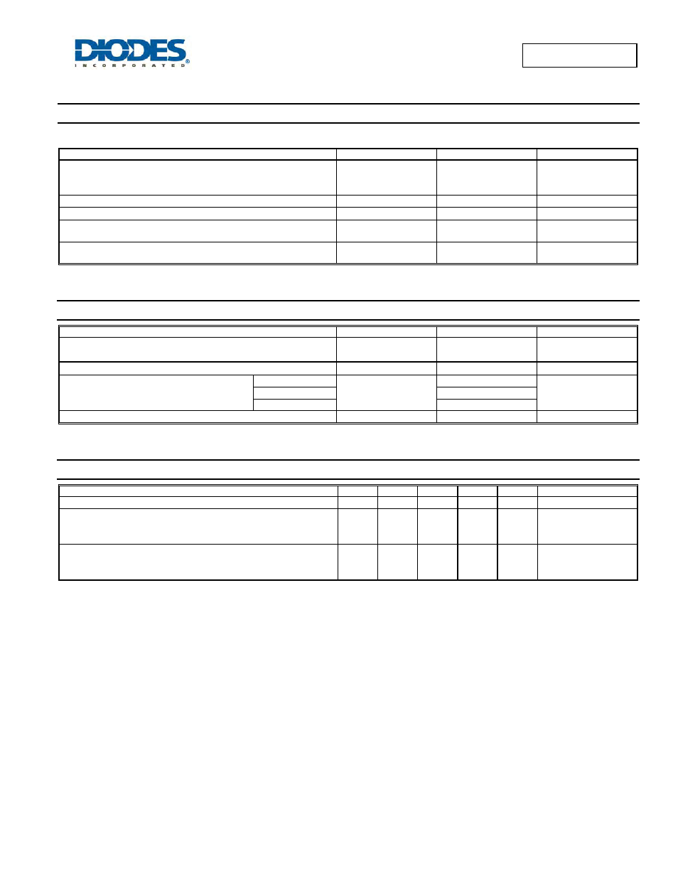
Maximum Ratings
(@T
A
= +25°C, unless otherwise specified.)
Single phase, half wave, 60Hz, resistive or inductive load.
For capacitance load, derate current by 20%.
Characteristic Symbol
Value
Unit
Peak Repetitive Reverse Voltage
Working Peak Reverse Voltage
DC Blocking Voltage
V
RRM
V
RWM
V
RM
45 V
RMS Reverse Voltage
V
R(RMS)
32 V
Average Rectified Output Current
I
O
10 A
Non-Repetitive Avalanche Energy
(T
J
= +25°C , I
AS =
20A , L = 8.5mH)
E
AS
20 mJ
Non-Repetitive Peak Forward Surge Current 8.3ms
Single Half Sine-Wave Superimposed on Rated Load
I
FSM
200 A
Thermal Characteristics
Characteristic Symbol
Value
Unit
Maximum Thermal Resistance
Thermal Resistance Junction to Ambient (Note 4)
R
θJA
54
°C/W
Thermal Resistance Junction to Lead (Note 4)
R
θJL
18 °C/W
Operating Temperature Range
V
R
≤ 80% V
RRM
T
J
-65 to +150
°C
V
R
≤ 50% V
RRM
≤180
DC Forward Mode
≤200
Storage Temperature Range
T
STG
-65 to +175
°C
Electrical Characteristics
(@T
A
= +25°C, unless otherwise specified.)
Characteristic Symbol
Min
Typ
Max
Unit
Test
Condition
Reverse Breakdown Voltage (Note 5)
V
(BR)R
45 — — V
I
R
= 0.5mA
Forward Voltage Drop
V
F
—
—
—
—
0.42
0.37
0.42
0.47
0.41
V
I
F
= 8A, T
J
= +25°C
I
F
= 10A, T
J
= +25°C
I
F
= 10A, T
J
= +125°C
Leakage Current (Note 5)
I
R
—
—
—
0.051
—
27
0.3
15
75
mA
V
R
= 45V, T
J
= +25°C
V
R
= 45V, T
J
= +100°C
V
R
= 45V, T
J
= +150°C
Notes:
4. FR-4 PCB, 2oz. Copper, minimum recommended pad lay
5. Short duration pulse test used to minimize self-heating effect.