Maximum ratings, Thermal characteristics, Electrical characteristics – Diodes SBR05U40CSP User Manual
Page 2
SBR is a registered trademark of Diodes Incorporated.
SBR05U40CSP
Document number: DS35768 Rev. 5 - 2
2 of 4
January 2014
© Diodes Incorporated
SBR05U40CSP
NEW PROD
UC
T
ADVANCED INFORMATION
ADVANCED INFORMATION
Maximum Ratings
(@T
A
= +25°C, unless otherwise specified.)
Single phase, half wave, 60Hz, resistive or inductive load.
For capacitance load, derate current by 20%.
Characteristic Symbol
Value
Unit
Peak Repetitive Reverse Voltage
V
RRM
40 V
Average Rectified Output Current
I
O
500 mA
Non-Repetitive Peak Forward Surge Current 8.3ms
Single Half Sine-Wave Superimposed on Rated Load
I
FSM
12 A
Thermal Characteristics
Characteristic Symbol
Value
Unit
Typical Thermal Resistance Junction to Ambient (Note 5)
R
θJA
130 °C/W
Operating and Storage Temperature Range
T
J
, T
STG
-55 to +150
°C
Electrical Characteristics
(@T
A
= +25°C, unless otherwise specified.)
Characteristic Symbol
Min
Typ
Max
Unit Test
Condition
Forward Voltage Drop
V
F
— 0.30 0.36
V
I
F
= 100mA
— 0.43 0.46
I
F
= 500mA
— 0.40 —
I
F
= 500mA, T
J
= +125°C
Reverse Current (Note 6)
I
R
— 4 15
µA
V
R
= 10V
— 8 75
V
R
= 40V
Junction Capacitance
C
j
— 34 — pF
V
R
= 4V, f = 1MHz
Notes:
5. Device mounted on FR-4 PCB, 2oz. Copper, minimum recommended pad lay
6. Short duration pulse test used to minimize self-heating effect.
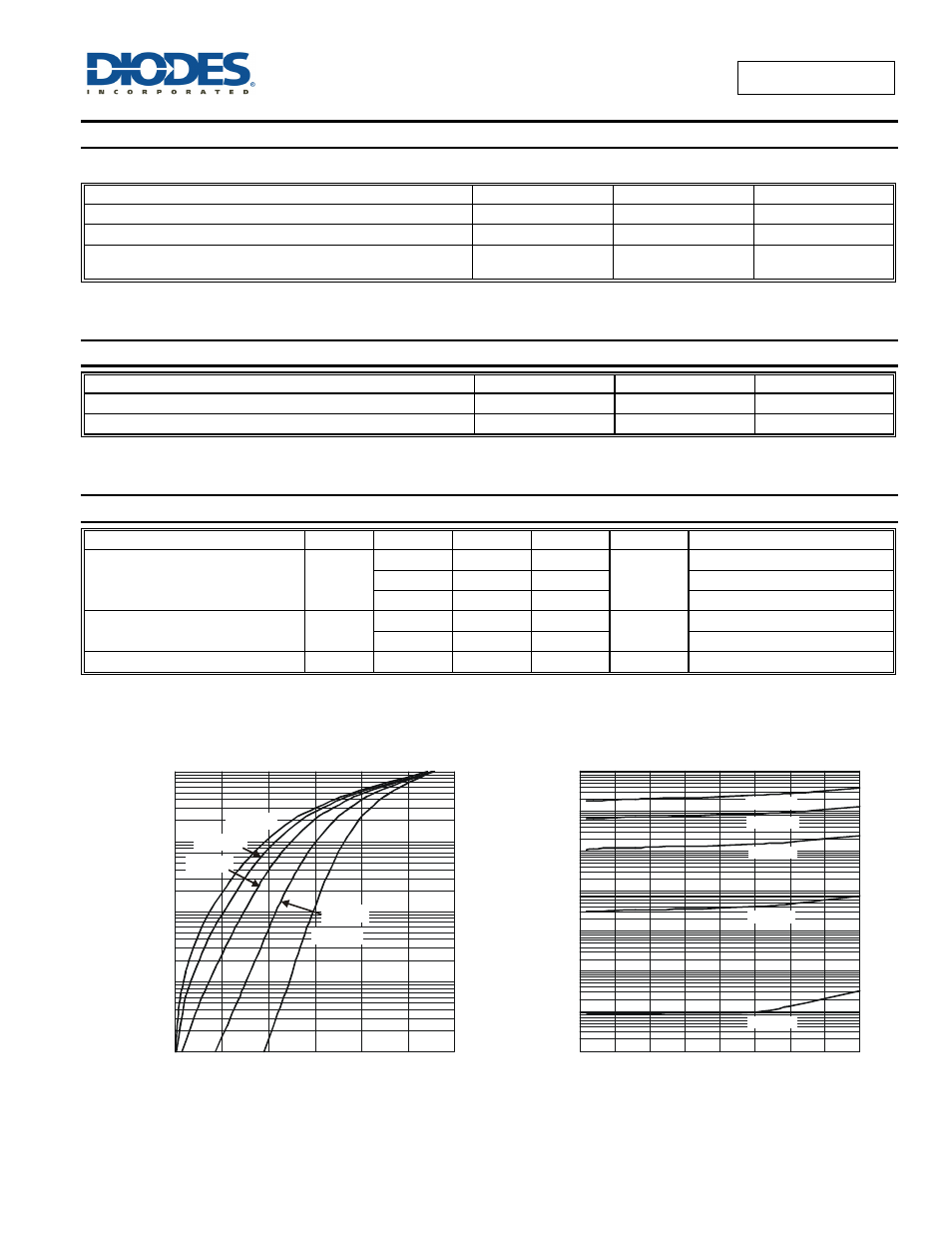
0.0001
0
0.1
0.2
0.3
0.4
0.5
0.6
0.001
0.01
0.1
1
I,
I
N
S
TAN
TANE
O
U
S F
O
R
WA
R
D
C
U
R
R
EN
T
(A
)
F
Figure 1 Typical Forward Characteristics
V , INSTANTANEOUS FORWARD VOLTAGE (V)
F
T = 25°C
A
T = 85°C
A
T = 125°C
A
T = 150°C
A
T = -55°C
A
0
5
10
15
20
25
30
35
40
I,
I
N
S
TA
N
TA
N
E
O
U
S
R
EV
E
R
SE
C
U
R
R
E
N
T
(µ
A
)
R
10,000
1,000
100
10
1
0.1
0.01
0.001
Figure 2 Typical Reverse Characteristics
V , INSTANTANEOUS REVERSE VOLTAGE (V)
R
T = 25°C
A
T = 85°C
A
T = 125°C
A
T = 150°C
A
T = -55°C
A