Maximum ratings, Thermal characteristics, Electrical characteristics – Diodes SBR1045SP5 User Manual
Page 2
SBR and POWERDI are registered trademarks of Diodes Incorporated.
SBR1045SP5
Document number: DS31370 Rev. 9 - 2
2 of 5
December 2012
© Diodes Incorporated
SBR1045SP5
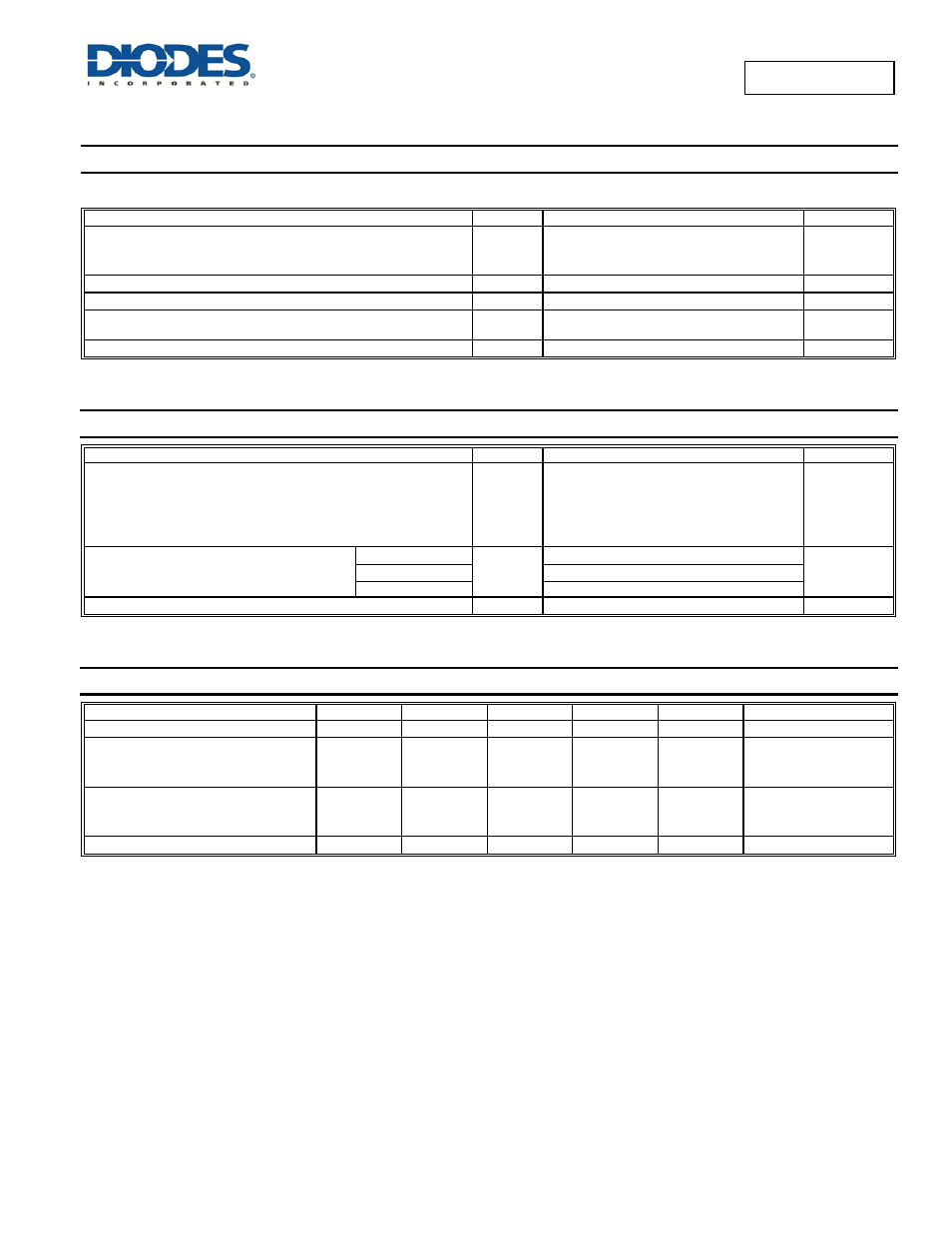
Maximum Ratings
(@T
A
= +25°C, unless otherwise specified.)
Single phase, half wave, 60Hz, resistive or inductive load.
For capacitance load, derate current by 20%.
Characteristic Symbol
Value
Unit
Peak Repetitive Reverse Voltage
Working Peak Reverse Voltage
DC Blocking Voltage
V
RRM
V
RWM
V
RM
45 V
RMS Reverse Voltage
V
R(RMS)
32 V
Average Rectified Output Current
I
O
10 A
Non-Repetitive Peak Forward Surge Current 8.3ms
Single Half Sine-Wave Superimposed on Rated Load
I
FSM
180 A
Repetitive Peak Avalanche Power (1
μs, +25°C)
P
ARM
10,000 W
Thermal Characteristics
Characteristic Symbol
Value
Unit
Typical Thermal Resistance
Thermal Resistance Junction to Lead
Thermal Resistance Junction to Case (Note 4)
Thermal Resistance Junction to Ambient (Note 4)
Thermal Resistance Junction to Ambient (Note 5)
R
θJL
R
θJC
R
θJA
R
θJA
3
6
102
60
ºC/W
Operating Temperature Range
V
R
≤ 80% V
RRM
T
J
-65 to +150
ºC
V
R
≤ 50% V
RRM
≤180
DC Forward Mode
≤200
Storage Temperature Range
T
STG
-65 to +175
ºC
Electrical Characteristics
(@T
A
= +25°C, unless otherwise specified.)
Characteristic Symbol
Min
Typ
Max
Unit
Test
Condition
Reverse Breakdown Voltage (Note 6)
V
(BR)R
45 - - V
I
R
= 0.5mA
Forward Voltage Drop
V
F
-
-
-
-
0.49
0.47
0.51
0.55
0.53
V
I
F
= 8A, T
J
= +25ºC
I
F
= 10A, T
J
= +25ºC
I
F
= 10A, T
J
= +125ºC
Leakage Current (Note 6)
I
R
-
-
-
0.03
-
17
0.45
18
100
mA
V
R
= 45V, T
J
= +25ºC
V
R
= 45V, T
J
= +100ºC
V
R
= 45V, T
J
= +150ºC
Typical Junction Capacitance
C
J
- 500 - pF
f = MHz, I
R
= 4V
Notes:
4. FR-4 PCB, 2oz. Copper, minimum recommended pad lay
5. Polymide PCB, 2oz. Copper, minimum recommended pad layout per
6. Short duration pulse test used to minimize self-heating effect.