Advanced instruments inc – Analytical Industries GPR-1535 GB Trace PPM Oxygen Transmitter User Manual
Page 9
Advanced Instruments Inc.
9
Recommendations to avoid erroneous oxygen readings and damaging the sensor:
¾ Do not place your finger over the vent (it pressurizes the sensor) to test the flow indicator when gas is flowing to the
sensor. Removing your finger (the restriction) generates a vacuum on the sensor and may damage the sensor (voiding the
sensor warranty).
¾ Assure there are no restrictions in the sample or vent lines
¾ Avoid drawing a vacuum that exceeds 14” of water column pressure – unless done gradually
¾ Avoid excessive flow rates above 5 SCFH which generate backpressure on the sensor.
¾ Avoid sudden releases of backpressure that can severely damage the sensor.
¾ Avoid the collection of liquids or particulates on the sensor, they block the diffusion of oxygen into the sensor.
¾ If the transmitter is equipped with an optional integral sampling pump (positioned downstream of the sensor) and a flow
control metering valve (positioned upstream of the sensor), completely open the flow control metering valve to avoid
drawing a vacuum on the sensor and placing an undue burden on the pump.
Moisture & Particulates: Installation of a suitable coalescing or particulate filter is required to remove condensation, moisture
and/or particulates from the sample gas to prevent erroneous analysis readings and damage to the sensor or optional
components. Moisture and/or particulates do not necessarily damage the sensor, however, collection on the sensing surface
can block or inhibit the diffusion of sample gas into the sensor resulting in a reduction of sensor signal output – and the
appearance of a sensor failure when in fact the problem is easily remedied by blowing on the front of the sensor. Consult the
factory for recommendations concerning the proper selection and installation of components.
Gas Connections: Inlet and outlet vent gas lines for ppm analysis require 1/8” stainless steel compression fittings; hard plastic
tubing with a low permeability factor can be used percentage range measurements.
Power Connection: Locate the appropriate power source to meet the analyzer or transmitter
requirements, ensure that
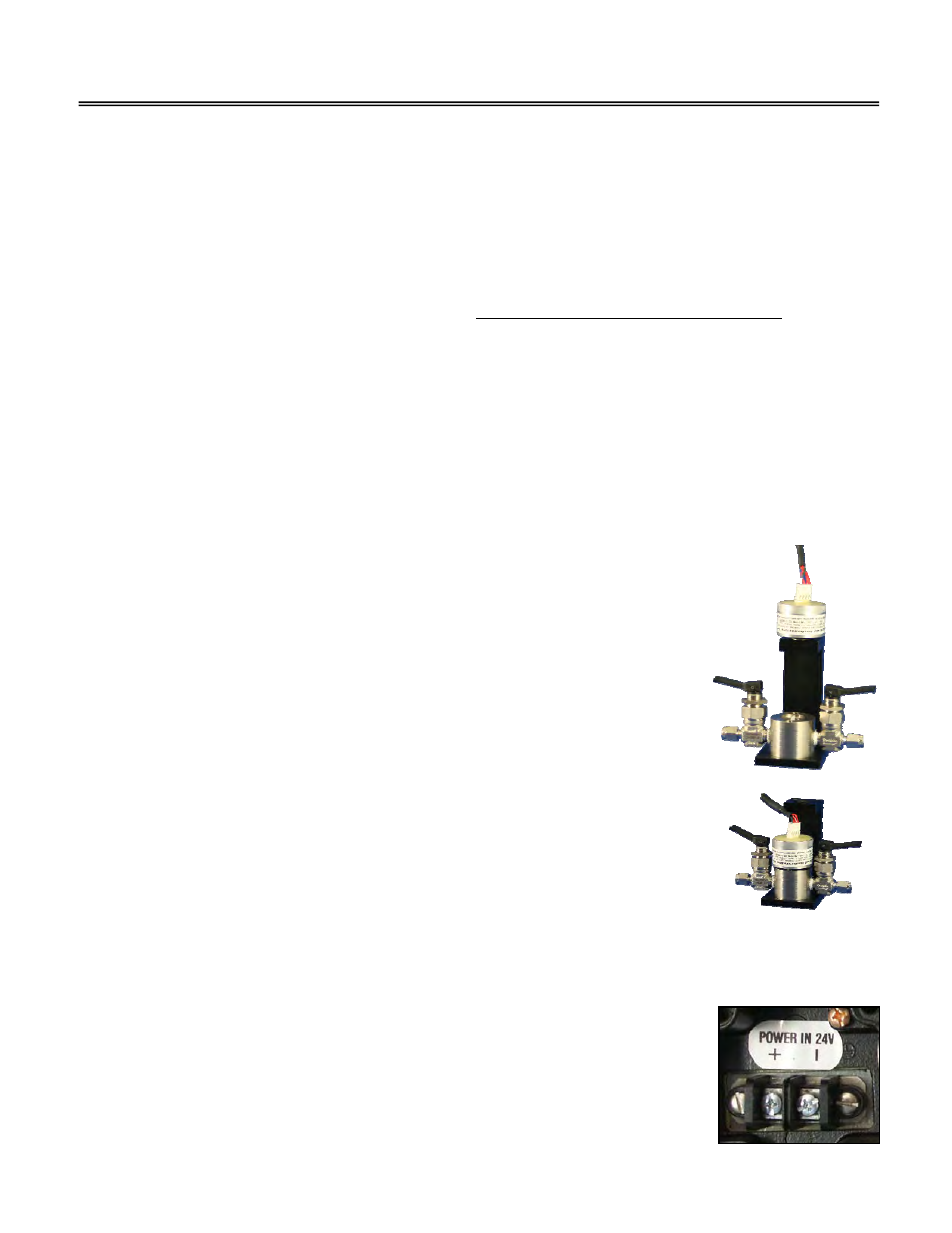
Mounting the Transmitter:
The GPR-1535 GB enclosure and Glove Box Housing Assembly are designed for any flat surface.
Gas Connections:
The GPR-1535 GB is designed for measuring a controlled atmosphere and requires only that the
sensor be screwed into the upper section of the Glove Box Housing Assembly.
Calibration: The user is responsible for calibration gases and regulating the pressure to 5-30 psig,
controlling the flow rate to 1-2 SCFH or .5-1 liter per minute and the plumbing to and from the Glove
Box Housing Assembly.
Caution: Do not place your finger over the vent (it pressurizes the sensor) to test the flow indicator when gas is flowing to the
sensor. Removing your finger (the restriction) generates a vacuum on the sensor and may damage the sensor (voiding the
sensor warranty).
Power Connection:
To assure proper grounding, connect the 4-20mA signal output to the external device (PLC, DCS,
etc.) before attempting any zero or span adjustments. Power requirements consist of a two wire
shielded cable and a 12-28V DC with negative ground power supply.