Asus b85m-e, F_panel, B85m-e system panel connector 10. intel – Asus B85M-E/BR User Manual
Page 25: B85m-e sata 3.0gb/s connectors
ASUS B85M-E
1-17
9.
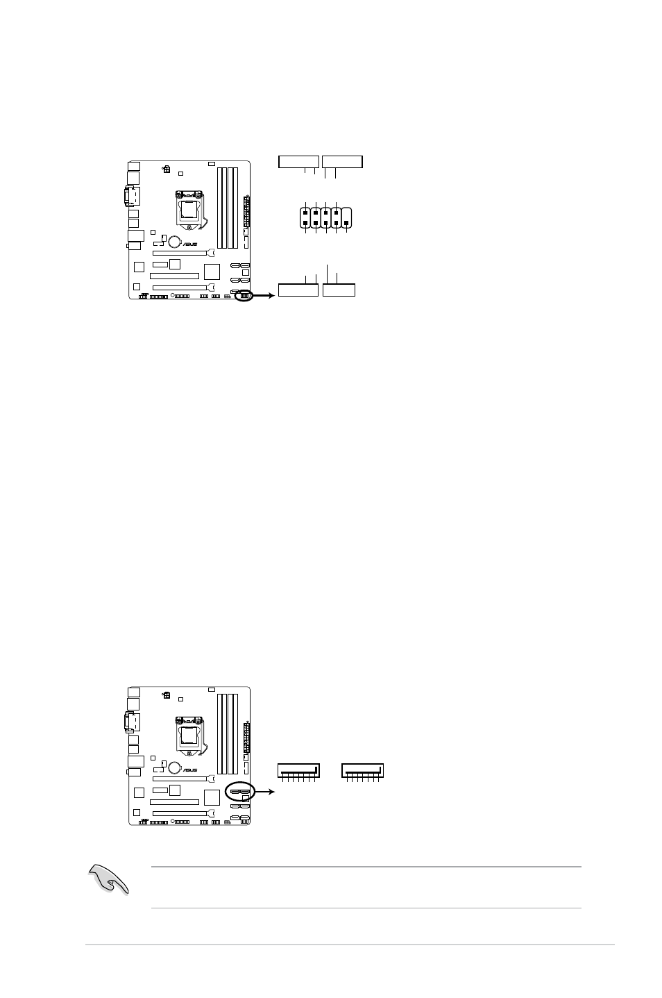
System panel connector (10-1 pin PANEL)
This connector supports several chassis-mounted functions.
•
System power LED (2-pin PWR_LED)
This 2-pin connector is for the system power LED. Connect the chassis power LED
cable to this connector. The system power LED lights up when you turn on the system
power, and blinks when the system is in sleep mode.
•
Hard disk drive activity LED (2-pin HD_LED)
This 2-pin connector is for the HDD Activity LED. Connect the HDD Activity LED cable
to this connector. The HDD LED lights up or flashes when data is read from or written
to the HDD.
•
ATX power button/soft-off button (2-pin PWR_BTN)
This connector is for the system power button.
•
Reset button (2-pin RESET)
This 2-pin connector is for the chassis-mounted reset button for system reboot without
turning off the system power.
B85M-E
PIN 1
PWR BTN
PLED+ PLED- PWR GND
HD_LED+ HD_LED-
Ground
HWRST#
(NC)
F_PANEL
PWR LED
+HD_LED
RESET
B85M-E System panel connector
10. Intel
®
B85 Serial ATA 3.0Gb/s connectors (7-pin SATA3G_1~2 [black])
These connectors connect to Serial ATA 3.0 Gb/s hard disk drives and optical drives via
Serial ATA 3.0 Gb/s signal cables.
When using hot-plug and NCQ, set the SATA Mode Selection item in the BIOS to [AHCI].
See section 2.6.3 SATA Configuration for details.
GND
RSATA_TXP1 RSATA_TXN1
GND
RSATA_RXN1 RSATA_RXP1
GND
SATA3G_2
SATA3G_1
GND
RSATA_TXP2 RSATA_TXN2
GND
RSATA_RXN2 RSATA_RXP2
GND
B85M-E
B85M-E SATA 3.0Gb/s connectors